


SAG584622000 System Application Guide
Issue AB, November 18, 2009 Spec. No. 584622000 (Model DCS4830)
Page 14 of 17
This document is property of Emerson Network Power, Energy Systems, North America, Inc. and contains confidential and proprietary information owned by Emerson Network Power, Energy
Systems, North America, Inc. Any copying, use, or disclosure of it without the written permission of Emerson Network Power, Energy Systems, North America, Inc. is strictly prohibited.
Home
1.4.3 Output Protection:
(A) Overvoltage Protection:
Operation of a DC-DC Converter Module will automatically shut
down and lock out if the output voltage of the module exceeds 115% to 125% of the nominal
voltage. Manual restart is necessary after the overvoltage condition is corrected.
(B) Overcurrent Protection: When the output current of a DC-DC Converter Module increases
to a preset overcurrent value between 102.5% and 115% of rated full load, the output
voltage of the module will automatically decrease to limit current to this value. The output
will recover to within specified limits when the overload condition is removed.
(C) Over Temperature Protection: The operation of a DC-DC Converter Module will
automatically shut down if the internal temperature of the module exceeds a predetermined
value. Operation will automatically resume after the over-temperature condition is corrected.
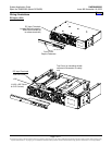
1.4.4 Series Paralleling Output Diode: A series paralleling output diode is provided in each
Converter Module. This allows the Converter Modules to be paralleled for redundancy.
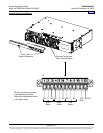
1.4.5 External Alarm Circuits: A set of Form-C relay contacts is provided for each of the following
alarms. Relays are energized for normal operating conditions and de-energized for an alarm
condition. Refer also to the
Wiring Notes and Wiring Illustrations section in this document, and
to the DC-DC Converter System “Installation and User Instructions” (Section 6035) for wiring
information.
(A) Converter Minor Alarm: Alarms in the event of a failure in one or more Converter Modules.
Converter failure alarm conditions are as follows.
(1) Converter output increases above 52 volts DC or decreases below 44 volts DC for any
reason; including converter failure, high voltage shutdown, input voltage below 21 volts
DC (low input inhibit), or an overload condition.
(2) Cooling fan slows or stops due to fan failure or blocked rotor.
(B) Converter Major Alarm: Alarms in the event of a failure in more than one Converter
Module. Converter failure alarm conditions are as stated in (A) above.
(C) Fuse Alarm: Alarms if any GMT load fuse opens.
1.4.6 Remote Shutdown Input (ESTOP): The Converter Modules can be inhibited by applying an
external ground signal (24V Return). Converter Modules automatically restart upon removal of
the ground signal. Refer to the DC-DC Converter System “Installation and User Instructions”
(Section 6035) for wiring information.
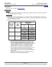
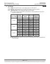
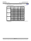
1.4.7 Local Status and Alarm Indicators and Test Points: Refer to the DC-DC Converter System
“Installation and User Instructions” (Section 6035) for a complete description.
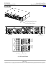
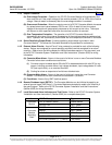
Location NAME / Description Type
ON / STANDBY Switch Rocker Switch
Converter
Module
OUTPUT OK LED - Green
MAJOR LED - Red
MINOR LED - Yellow
INPUT OK LED - Green
FUSE ALARM LED - Red
Converter
Module
Mounting
Shelf
SYSTEM CURRENT (+, -) (1A/mV) Test Points