


CTP150CM Remote Control Panel • Installation and Operation
CTP150CM Remote Control Panel • Installation and Operation
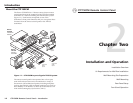
Installation and Operation, cont’d
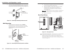
5b. If you are using a wall box, insert the wall box into the
opening, and attach it to the wall stud or furniture with
nails or screws, leaving the front edge flush with the outer
wall or furniture surface (figure 2-3). The illustration
applies to both two-gang and four-gang wall boxes.
Wall opening
flush with
edge of box
Installation
Cable
Cable Clamp
Screws or Nails
Wall Stud
Figure 2-3 — Attaching a wall box to a stud
If attaching the wall box to wood, use four #8 or #10
screws or 10-penny nails. A minimum of 1/2 inch (1.3 cm)
of screw threads must penetrate the wood.
If attaching the wall box to metal studs or furniture, use
four #8 or #10 self-tapping sheet metal screws or machine
bolts with matching nuts.
2-52-4
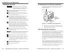
Installation using a UL listed wall box (available from Extron) is
recommended for most mounting options, but the optional wall
mounting bracket can be used instead. All wall boxes must be
at least 1.0" (2.5 cm) deep.
Before using the wall mounting bracket, verify that the
installation conforms to national and local electrical
codes.
Prepare the site as follows:
1. If your wall box or mounting bracket includes a paper
template, cut out the indicated portions of the template.
If the wall box or mounting bracket does not include a
template, use the wall box or bracket itself to size the hole.
2. Place the template, wall box, or mounting bracket against
the installation surface, and mark the guidelines for the
opening on the wall or furniture.
3. Cut out the wall/furniture material from the marked area.
4. Check the opening size by inserting the wall box or
mounting bracket into the opening. The box or bracket
should fit easily into the opening. Enlarge or smooth the
edges of the opening if needed.
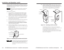
5a. If you are using a wall box, feed cables through the wall
box punch-out holes, and secure them with cable clamps to
provide strain relief.
Exposed cable shields (braids or foil) are potential sources
of short circuits. Trim back and/or insulate shields with
heat shrink (figure 2-2).
Metal Wall Box
Screw
Braided Shield
Install Cable
Foil Shield
Cable Clamp
Figure 2-2 — Grounding outer braided and foil shields
To prevent short circuits, the outer foil shield can be
cut back to the point where the cable exits the cable
clamp. Both braided and foil shields should be
connected to an equipment ground at the other end
of the cable.