


CTP150CM Remote Control Panel • Installation and Operation
CTP150CM Remote Control Panel • Installation and Operation
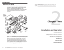
Installation and Operation, cont’d
2. If not already accomplished, attach the 8-conductor cable
to the rear of the remote control panel.
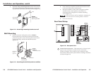
3. Mount the CPM101 or other mini-AAP panel (with the
attached remote control panel) to the wall box or
mounting bracket using the two included mounting
screws (figure 2-5).
Figure 2-5 shows a wall box installation. Mounting the
mini-AAP panel to a mounting bracket is identical.
4. Power on all devices.
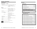
Rear Panel Setup
GND
PROJ PWR
VOL DN
VOL UP
IN4
IN3
IN2
IN1
CONTACT
CLOSURE
MADE IN USA
GND
PROJ PWR
VOL DN
VOL UP
IN4
IN3
IN2
IN1
CONTACT
CLOSURE
TPT150
Switching
Transmitter
Input 1
Input 2
Input 3
Input 4
Volume up
Volume down
Projector power
Ground
CTP150CM Control Panel
1
Figure 2-6 — Rear panel view
1
Contact closure connector — This connector is a 3.5 mm, 8-pole
captive screw connector for contact closure connections.
Connect a Category (Cat) 5 cable or any 8-conductor cable
between the remote control panel and the switching transmitter,
as shown in figure 2-6.
2-72-6
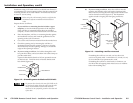
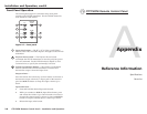
6. If you are using a mounting bracket, follow the directions,
if any, that came with the mounting bracket to attach the
clips that fasten the bracket to the wall or furniture (figure 2-4).
Push Mounting
Tabs Forward
Wall
Extron
IN9181 Wall
Mounting Bracket
Figure 2-4 — Attaching a mounting bracket to a wall
Wall Mounting
1. Sandwich the mini-AAP panel (such as a CPM101)
between the body of the remote control panel and the
printed front panel. Secure the front panel to the remote
control panel body with the included #4-40 screws
(figure 2-5).
Wall opening
flush with
edge of box
Front Panel
Extron
CTP150CM
Control Module
Extron
CPM101
A/V Connector Panel
PC 1
PC 2
VIDEO 1
VIDEO 2
VOL
UME
UP
DOWN
PROJECTOR
POWER
Figure 2-5 — Attaching the mini-AAP panel to a wall box