


DTP T HWP 231 D and DTP T HWP 331 D Transmitters • Installation and Operation 8
Transmitter Rear Panel
Tx Rx Tx Rx
RS-232 IR
G
HDBT
DTP
OVER TP
OUT
POWER
12V
A MAX
- -
DTP T HWP 231/331 D
Rear Panel
A
B
C
D
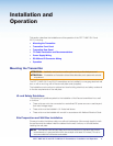
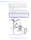
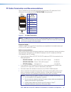
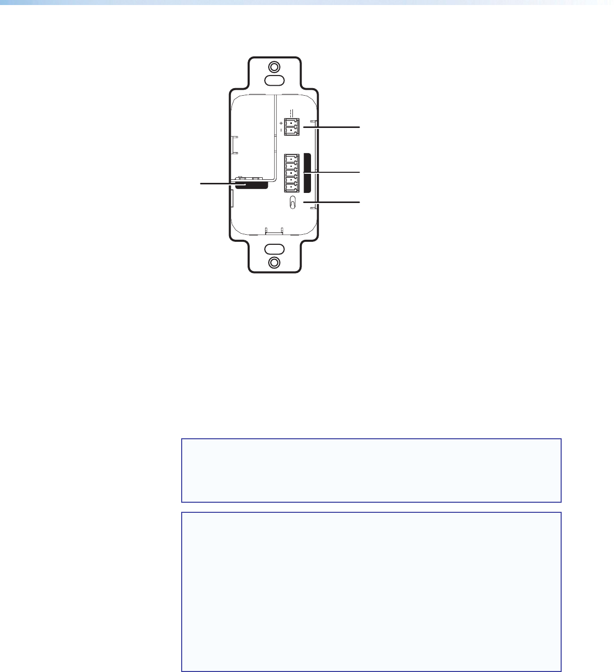
Figure 7. DTP T HWP 231 D and 331 D Transmitter Rear Panel Connectors
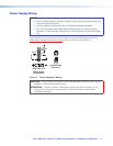
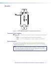
A DC power input connector — Plug the included external 12 VDC power supply into
either this 2-pole connector (see Power Supply Wiring on page 11 to wire the power
connector) or the power input connector on a compatible receiver.
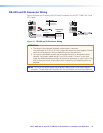
B Over TP connector — Connect a serial communications port to this 3.5 mm, 5-pole
captive screw connector for bidirectional RS-232 communication and bi-directional IR
(see RS-232 and IR connector wiring on page 13 to wire the connector).
C HDBaseT/DTP mode switch — Set this 2-position, recessed switch to configure
the output between HDBaseT and DTP modes. When configured for HDBaseT, use
an HDBaseT-compatible receiver. When configured for DTP, use a DTP-compatible
receiver.
NOTE: When the unit is configured for DTP mode via the rear panel switch, the unit
can be powered either locally, with the included external 12 VDC power supply,
or over the DTP line by a locally powered receiver or switcher. When configured
for HDBaseT mode, remote power capability is disabled, and the unit must be
powered locally.
NOTES:
• When the unit is configured for DTP mode via the rear panel switch, the unit
can be powered either locally, with the included external 12 VDC power
supply, or over the DTP line by a locally powered receiver or switcher. When
configured for HDBaseT mode, remote power capability is disabled, and the
unit must be powered locally.
• When configured for DTP mode, HDMI video, digital embedded audio, RS-
232, IR, analog audio, and remote power are available when used with a DTP-
compatible receiving device.
• When configured for HDBaseT mode, HDMI video, digital embedded audio,
RS-232, and IR are available when used with an HDBaseT-compatible
receiving device.