


DVI-RGB 100 • Installation 3DVI-RGB 100 • Installation
Installation
2
Overview
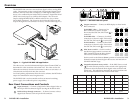
The DVI-RGB 100 converter converts direct digital video to analog RGB
video. The converter accepts a single link of digital-only Digital Visual
Interface (DVI-D) video from a computer, or other digital video source
device, on a standard 25-pin female DVI-D connector. Digital Flat Panel
(DFP) video can be input via a DFP-to-DVI adapter. The converter
outputs analog RGBHV, RGBS, or RGsB video on five, four, or three
female BNC connectors. The converter also buffers the DVI input and
loops it through on a DVI connector for use by a local monitor (figure 1).
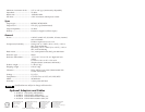
Power High Resolution Workstation
Projector
100-240 50/60 Hz
0.35A MAX
O
U
T
P
U
T
I
N
P
U
T
B
U
F
F
E
R
E
D
L
O
O
P
-
T
H
R
O
U
G
H
R
H
G
V
B
S
SOG ON/OFF
SPARE
D
D
C
S
O
U
R
C
E
M
O
N
I
T
O
R
S
E
L
E
C
T
O
R
O
U
T
P
U
T
R
E
S
O
L
.
DVI-RGB 100
Figure 1 — Typical DVI-RGB 100 application
The video source uses the bidirectional Display Data Channel (DDC) to
determine the video resolution and refresh rate. The video source can
obtain the rate directly from the local monitor or the user can select 1 of
14 resolutions and rates built into the converter.
Level and peaking adjustments allow the user to enhance the RGB video
output for transmission across long distances.
The DVI-RGB 100 is rack mountable and has an internal switching
power supply for worldwide power compatibility.
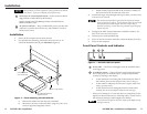
Rear Panel Connections and Controls
1
Input connector — Connect a single link of direct digital video to
this 25-pin DVI-D connector (figure 2) using the included cable.
2
Buffered Loop-through connector — If desired, connect a direct
digital local monitor to this 25-pin DVI-D connector.
100-240 50/60 Hz
0.35A MAX
OUTPUT
INPUT
BUFFERED
LOOP-THROUGH
R
H
G
V
B
S
SOG ON/OFF
SPARE
DDC
SOURCE
MONITOR
SELECTOR
OUTPUT
RESOL.
21 57
346
Figure 2 — DVI-RGB 100 rear panel
3
Output connectors — Connect an RGB display to these female
BNC connectors.
For RGBHV video — Connect to five
BNC connectors as shown at right.
Ensure that the SOG On/Off switch (
6
) is
turned off.
For RGBS video — Connect to four BNC
connectors as shown at right. Ensure that
the SOG On/Off switch (
6
) is turned off.
For RGsB video — Connect to three BNC
connectors as shown at right. Ensure that
the SOG On/Off switch (
6
) is turned on.
4
DDC Source switch — Set this switch to
the Monitor (up) position to connect the
DDC channel between the direct digital
video source and the local monitor.
Set this switch to the Selector (down) position to connect the DDC
channel between the direct digital video source and the built-in
DVI-RGB 100 DDC logic.
5
Output Resol.(ution) rotary switch — If the DDC Source switch
(
4
) is in the Selector position, set this switch to the appropriate
position to select the desired direct digital video resolution and
refresh rate. The table below identifies the switch positions and
the associated resolutions and vertical refresh rates.
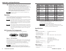
.soPnoituloseRetaR.V.soPnoituloseRetaR.V.soPnoituloseRetaR.V
0084x046065 084x25806A 4201x082106
1084x046576 867x420106B 4201x082157
2006x008067 867x420157C 4201x563106
3006x008578 4201x420106D 027x082106
4084x848069 567x082165F,EerapS
R
H
G
V
B
S
R
H
G
V
B
S
R
H
G
V
B
S