


DVI-RGB 100 • Installation and Operation 5DVI-RGB 100 • Installation
Installation
4
Many monitors will not support all of the resolutions and refresh
rates shown. If you get no display, try a different rate.
6
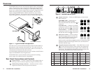
SOG (Sync on Green) On/Off switch— Set this switch to the On
(up) position to enable SOG for RGsB video.
Set this switch to the Off (down) position to disable SOG for
RGBS or RGBHV video.
7
AC power connector — Plug a standard IEC power cord into this
connector to connect the converter to a 100 to 240VAC, 50 Hz or
60 Hz power source.
Installation
1. Power off the computer and its local monitor.
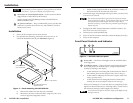
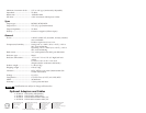
2. For optional rack mounting, mount the converter on a 19" 1U
Universal Rack Shelf (Extron part #60-190-01) (figure 3).
(2) 4-40 x 3/16" Screws
Use 2 Mounting Holes on
Opposite Corners
False Front Panel
uses 2 front holes
D
V
I
-
R
G
B
1
0
0
D
V
I T
O
R
G
B
C
O
N
V
E
R
T
E
R
B
O
O
S
T
L
E
V
E
L
C
O
N
T
R
O
L
P
E
A
K
Figure 3 — Rack mounting the DVI-RGB 100
a. Remove the rubber feet from the case if installed.
b. Mount the converter on the rack shelf, using two 4-40 x 3/16
screws in opposite (diagonal) corners.
c. Install a blank panel (included in the rack kit) or another 1U
half-rack unit on the unused side of the rack.
3. Connect the input, loop-through and output cables. See Rear Panel
Connections and Controls.
The maximum permissible length of the DVI input and output
cables is 16.4 feet (5 meters). Ensure that the cables do not exceed
the maximum permissible length, otherwise images may be
distorted or missing. Extron does not guarantee signal integrity
beyond 16.4 feet.
4. Configure the DDC, Output Resolution, and SOG switches. See
Rear Panel Connections and Controls.
5. Connect power to the DVI-RGB 100.
6. Power on the local monitor and other connected display device(s).
7. Power on the computer
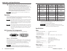
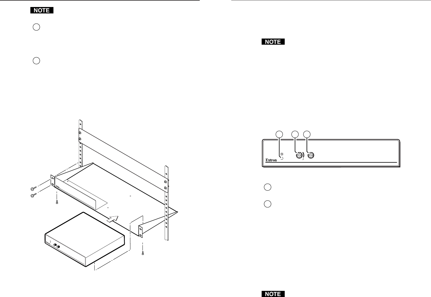
Front Panel Controls and Indicator
DVI-RGB 100
DVI TO RGB CONVERTER
BOOST
LEVEL
CONTROL
PEAK
8 9 10
Figure 4 — DVI-RGB 100 front panel
8
Power LED — The Power LED lights when the DVI-RGB 100 is
receiving power.
9
Level Boost control — The Level Boost control alters the bright-
ness of the picture on the RGB output. Judge the adjustment
visually by looking at the display.
• At the minimum level setting (the counterclockwise limit of
this control), the converter outputs video at 0.5 volts p-p.
• At the control’s midpoint, the converter outputs video at 0.7
volts p-p (unity level).
• At the maximum level setting (the clockwise limit of this
control), the converter outputs video at 1.45 volts p-p.
Select a level setting of 0.7 volts and above to compensate for the
signal level decrease that occurs with long cables. Set the level at
the maximum setting for cable lengths over 500 feet.
Level Boost has no affect on the DVI output of the Buffered Loop-
through connector.