


2-5IN1502 • Installation and Operation
Rear Panel Features
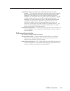
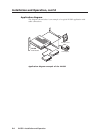
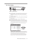
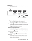
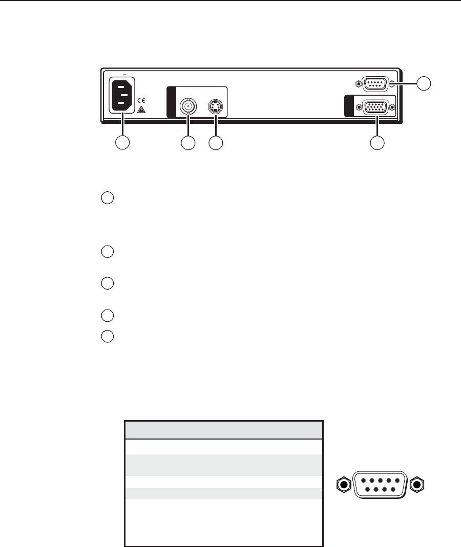
The rear panel of the IN1502 is shown below.
50/60 Hz
1
2
REMOTE
RGB
S-VIDEOCOMPOSITE
100-240V 0.3A
I
N
P
U
T
S
O
U
T
1
2 3
4
5
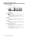
IN1502 rear panel connectors
1
AC power connector — Plug a standard IEC power cord into this connector
to connect the scaler to a 100 to 240 VAC, 50 Hz or 60 Hz power source.
The front panel LCD display and input selection LEDs will light during
power-up.
2
Video input 1: Composite video — Connect a composite video signal to this
female BNC connector.
3
Video input 2: S-video — Connect an S-video signal to this 4-pin mini-DIN
female connector.
4
RGB 15-pin HD video output — Connect an RGB video display.
5
Remote (RS-232/contact closure) 9-pin port — This connector provides for
two-way RS-232 communication and contact closure control. See chapter 3,
“Serial Communication”, for information on how to use the SIS commands.
The default protocol is 9600 baud, 1 stop bit, no parity, and no flow control.
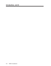
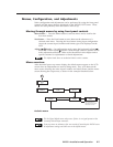
The rear panel RS-232 9-pin D female connector has the following pin
assignments:
Pin RS-232 function Description
1 – No connection
2 Tx Transmit data
3 Rx Receive data
4 Input #1 Contact closure
5 Gnd Signal ground
6 Input #2 Contact closure
7 – No connection
8 – No connection
9 Hardwired IR IR input
DB9 Pin Locations
Female
51
96
The Remote connector also provides a way to select an input using a remote
contact closure device. Contact closure control uses pins on the Remote
connector that are not used by the RS-232 interface (see preceding the table).
To select a different input number using a contact closure device,
momentarily short the pin for the desired input number to logic ground
(pin 5). To force one of the inputs to be always selected, leave the short to
logic ground in place. The short overrides front panel input selections.