TP Receivers • Installation and Operation
TP Receivers • Installation and Operation
Installation and Operation, cont’d
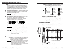
5. For through-surface mounting (all except TP R 15HD A),
insert four #8 wood screws through the bracket and into
the four pilot holes. Tighten all four screws to secure the
receiver in place.
6. For under-surface mounting, insert #8 wood screws into
the four pilot holes. Tighten each screw into the mounting
surface until just less than 1/4” of the screw protrudes.
7. For under-surface mounting, align the mounting screws
with the slots in the brackets and place the receiver against
the surface, with the screws through the bracket slots.
8. For under-surface mounting, slide the receiver slightly
forward or back, then tighten all four screws to secure the
switcher in place.
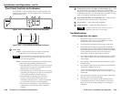
Projector mounting
All of the receiver models can be mounted on a projector
bracket using the appropriate optional mounting bracket,
Extron’s Mini Projector Mounting Kit (part #70-217-01)
(TP R 15 HD A) or Projector Mounting Kit (part #70-077-04)
(all other models).
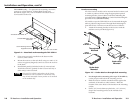
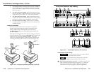
Secure the mounting bracket to the receiver using two machine
screws in the side of the receiver (TP R 15HD A) or the three #8
machine screws provided (all other models). Secure the
receiver to a projector mount or other surface by inserting the
mounting bolt through the bracket’s slotted hole (figure 2-6).
A
A
-V
O
U
TP
UT
O
U
TP
U
T
P
O
W
E
R
1
5
V
.
5
A
D
C
L
R
B
A
V
I
N
P
U
T
V
I
D
E
O
TP R AV
TP R 15HD A
Mounting
Bolt
C
S
Y
N
C
S
O
G
C
V
I
D
E
O
N
/
C
L
R
A
U
D
I
O
O
U
T
P
U
T
A
V
I
N
P
U
T
R
G
B
P
O
W
E
R
1
5
V
.
3
4
A
M
A
X
Mounting
Bolt
Projector
Mounting
Bracket
Projector
Mounting
Bracket
Figure 2-6 — Projector bracket mounting a receiver
2-10
Rear panel features and cabling
TP R BNC A
TP R BNC AV
TP R AV
RGB INPUT
A-V INPUT
50/60 Hz
100-240V 0.3A
RGB OUTPUT
R
VIDEO
G B H/HV V
A
AUDIO
AUDIO
L
R
B
SOG
C SYNC
LR
A
A-V AUDIO
L
R
B
LR
RGB INPUT
RGB OUTPUT
R G B H/HV V
A
AUDIO
L
R
B
SOG
C SYNC
POWER
15V .5A DC
LR
TP R 15HD A
A
A-V OUTPUT
L
R
B
A-V INPUT
VIDEO
AUDIO
POWER
15V .5A DC
LR
C SYNC
SOG
C VIDEO
N/C
LR
AUDIO
OUTPUT
AV INPUT
RGB
POWER
15V
.34A MAX
9
5
5
8
2 6 7 8 9
8
1
7
5
3
2 6 7 8 9
1 4 8 9
1
3
7
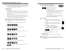
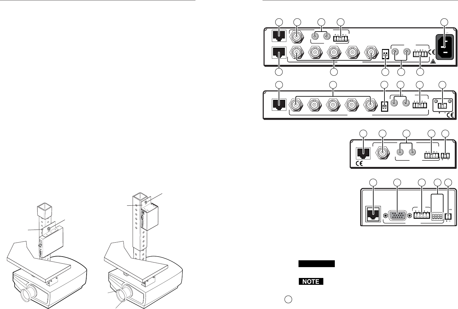
Figure 2-7 — Installation features, TP receivers
Transmitted signal cabling
CAUTION
Do not connect this device to a computer data or
telecommunications network
RJ-45 termination must comply with the TIA/EIA
T 568A wiring standards for all connections.
1
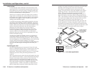
RGB video transmission connector — Attach one end of a TP
cable to this RJ-45 female connector (figure 2-7). Attach the
other end to an Extron TP 15HD or BNC transmitter. See
Termination of TP cable on page 2-15 for pin assignments.
2-11


