PRELIMINARY
1
The Extron WMK 100 Wall Mounting Kit is used for hanging PoleVault
®
System A/V products on a wall near
a flat screen display or short throw projector.
The WMK 100 has a 13" x 13" x 2.5" deep enclosure to mount the
PoleVault switcher and the power supply, with room for cable
management. It also has knockouts on all four sides which allow
external raceways to be used where necessary for cabling.
C
Maximum load for the WMK 100 is 15 lbs (7 kg)
.
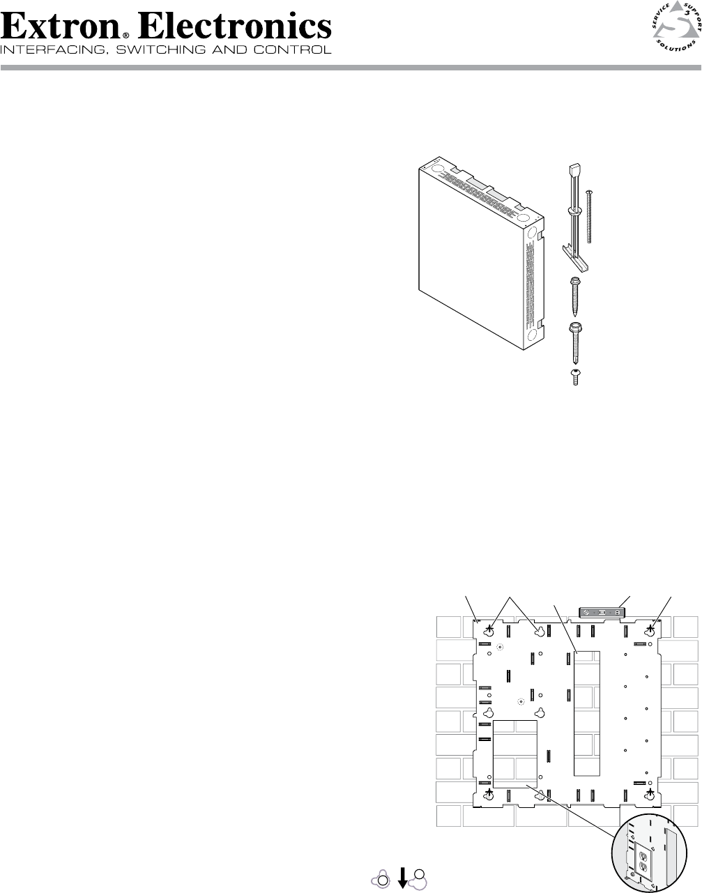
The key components (base plate and cover) of the WMK 100 are
shown in figure 1.
Included in the kit are:
(4) ¼-20 x 2" pan head bolts, (4) ¼" Kap toggle assemblies,
(4) ¼ x 1¾" masonry screws, (4) #14 x 1¾" self tapping metal/wood
screws, (4) 6-32 x ¼" button head hex screws.
Not shown but included are (3) 4-40 x ¼" screws, (2) hook-and-loop
straps.
Installation
N
Refer to local building standards and codes to verify that the installation will meet the regulatory
requirements. Observe all local and national building and safety codes, UL requirements, and ADA
accessibility guidelines.
Before installation identify the type of wall (masonry or non-masonry) and the location where the WMK 100 will be
installed. This determines the installation approach and the type of fasteners needed to secure the plate to the wall.
1. Mount the base plate
Follow the steps within 1A or 1B below, as applicable.
N
The base plate can be installed over an existing electrical
outlet. The opening fits standard sized 2.75" x 4.5" wall
plates. See figure 2 (inset).
1A. To mount the WMK 100 onto masonry walls:
i. Hold the base against the wall, level it, and mark the
positions of four slotted mounting holes (indicated by
+ marks in figure 2). Set the plate aside.
N
Use the top slot position at each mounting hole. Do not use
both top and left slots as this will make it difficult to slide the
plate down (see step iv).
ii. Using a masonry drill bit, drill 1.75" (4.4 cm) deep pilot holes
at the marked locations.
iii. Screw in masonry screws until a gap of 1/8" to 3/8"
(3 to 9 mm) remains between the wall and the screw heads.
iv. Align the base plate's slotted mounting holes over
the installed screws, then slide the plate down so
the screws fit into the slots.
v. At this time, lightly tighten all the screws to secure the plate
to the wall and verify level and position.
N
Do not over tighten, as the plate needs to be removed to attach the
switcher and power supply before cabling.
Proceed to Step 2.
The plate can be aligned over an existing electrical outlet.
WMK 100 Installation Notes
Figure 1 — WMK 100 parts
68-1738-01
Rev A
06 09
Figure 2 — Masonry wall mounting
(4) 1/4" x 1 3/4" Masonry Screws
#40-373-01
(4) #14 x 1 3/4" Self-tapping
Metal/Wood Screws
#40-372-01
(4) 1/4-20 x 2"
Pan Head Bolts
#40-375-01
(4) 1/4" Kap Toggle Assemblies
#40-374-01
(4) 6/32" x 1/4" Button Head
Hex Screws
#40-363-17LF
Cutout for
Electrical
Outlet
Level
Cutout for
Signal Cable
Access
Marker for
Pilot Hole
WMK 100
Base Plate
Mounting
Holes


