


PRELIMINARY
WMK 100 Installation Notes, cont'd
2
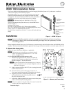
1B. To mount the WMK 100 onto a non-masonry wall:
i. At the desired site locate the wall studs and mark their
locations.
N
For ideal installation secure the base plate to at least one
wall stud (see figure 3). Drywall Kap toggles can be used
for holes not aligned with studs.
The base plate can be installed over an existing electrical
outlet. The opening fits standard sized 2.75" x 4.5" wall
plates. See inset on figure 2.
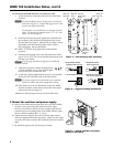
ii. Hold and level the base plate against the wall and mark
the positions of the slotted mounting holes that are on
the stud lines (see figure 3, indicated by + marks). Where
applicable, mark the mounting holes on the wall for
drywall toggles. Set the plate aside.
iii. Drill 1.75" (4.4 cm) deep pilot holes at the marked
locations.
iv. Insert the self tapping screws into the pilot holes, until a
gap of 1/8" to 3/8" (3 to 9 mm) remains between the wall
and the screw heads.
N
If using toggle assemblies see figure 4 for installation
method.
v. Align the base plate's slotted mounting holes
over the installed screws, then slide the plate
down so the screws fit into the slots.
vi. At this time, lightly tighten all the screws to ensure plate
fits flush to the wall and verify level and position.
N
Do not over tighten, as the plate needs to be removed to
attach the switcher and power supply before cabling.
vii. If the cables are to be run behind the wall to the WMK
location, mark the cutout area on the wall for the signal
cable access hole (see figure 3).
viii. Remove the base plate and cut out the marked area.
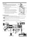
2. Mount the switcher and power supply
a. Remove the WMK 100 base plate from the wall, and with the
switcher's rear ports facing the cable access hole, align
the two corner holes in the base of the switcher with the two
outermost device mounting holes in the WMK 100 base plate.
Secure with the supplied 440 x ¼" screws.
b. Attach the power supply above the electrical outlet cutout,
with the supplied hook-and-loop straps. Attach it so the cables
are easily and safely routed to the electrical outlet and switcher
alike.
c. Re-attach the plate to the wall and secure firmly.
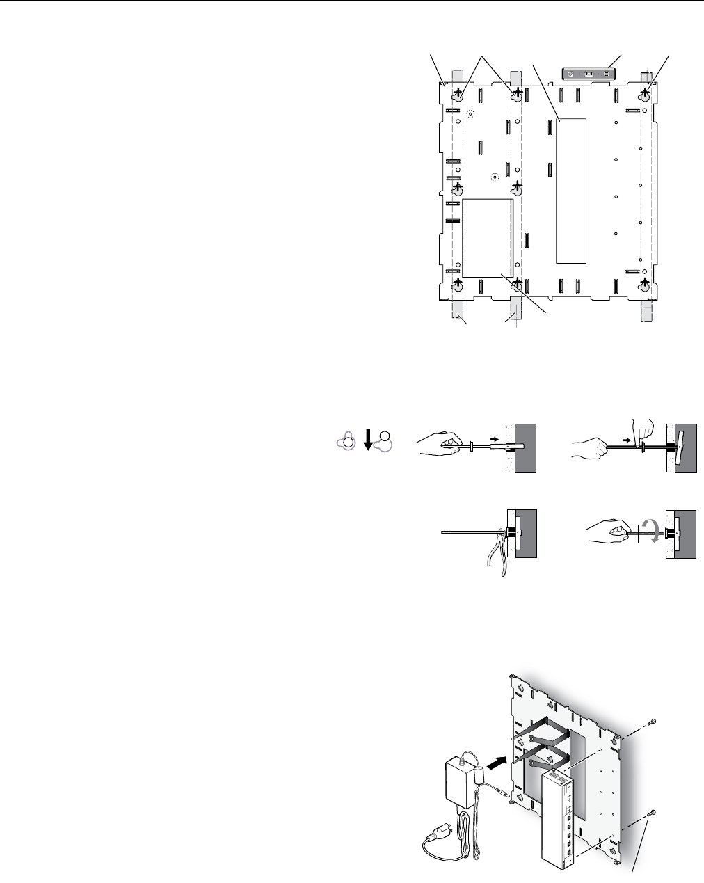
Figure 3 — Non-masonry wall mounting
Wall Studs
Cutout for
Electrical
Outlet
Level
Cutout for
Signal Cable
Access
Marker for
Pilot Hole
WMK 100
Base Plate
Mounting
Holes
+
+
(2) 4-40 x 1/4" screws
(2) 4
-
40x1/4
"
sc
rew
s
PVS 305SA
POLEVAULT SWITCHER
INPUT SELECTION
1
2
PEAK
NORMAL
SIGNAL
CONFIG
3 4
5
AUX AUDIO
AUDIO LEVEL ADJUST
PAGING
SENSOR
SENSITIVITY
VOICELIFT
MIC
PEAK
NORMAL
SIGNAL
INPUT
Figure 4 — Toggle assembly installation
a. Grasp handle, collapse
toggle and insert into wall.
b. Slide plastic washer
down into pilot hole.
c. Cut off handle close to wall.
d. Hand screw in pan head
bolt until 1/8" gap remains.
Figure 5 — Attach switcher and power
supply to base plate