


- 78 -
Channel Expander
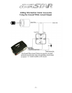
The channel expander is an add-on module that can be used to expand the existing two
auxiliary outputs to a total of seven auxiliary outputs. Each one of these seven outputs
can be individually programmed for pulsed, latched, or timed-latch output. The
programming of the Channel Expander outputs must be done with the Option
Programmer; the CompuStar remotes do not have the ability to access these programming
options.
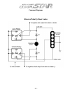
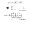
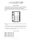
12v+ 3
Aux1 In 2
Input
GND 1
12v+ 8
Aux 7 ( – )200mA 7
Aux 6 ( – )200mA 6
Aux 5 ( – )200mA 5
Aux 4 ( – )200mA 4
Aux 3 ( – )200mA 3
Aux 2 ( – )200mA 2
Output
Aux 1 ( – )200mA 1
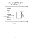
Connector 1 - Input
Pin1: This is the ground wire for the Channel Expander. Ground this wire to the vehicle
chassis.
Pin2: This is the data input wire used to communicate with the CompuStar brain module.
Connect this wire to the Aux 1 output wire from the CompuStar brain module.
Pin3: This is the 12v constant wire for the Channel Expander. Connect this wire to a
constant 12v+ source within the vehicle.
Connector 2 - Output
Pin1: Aux 1, 200mA negative output.
Pin2: Aux 2, 200mA negative output.
Pin3: Aux 3, 200mA negative output.
Pin4: Aux 4, 200mA negative output.
Pin5: Aux 5, 200mA negative output.
Pin6: Aux 6, 200mA negative output.
Pin7: Aux 7, 200mA negative output.