


17
Installation
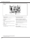
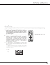
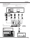
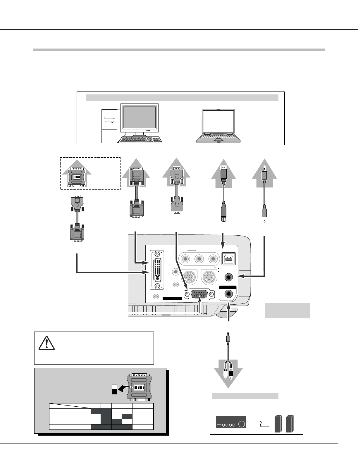
Connecting to a Computer
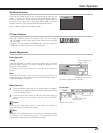
ONON
COMPUTER IN 1
DVI - I
MONITOR OUT
S-VIDEO
COMPUTER IN 2 /
COMPONENT IN /
COMPUTER /
COMPONENT
AUDIO IN
AUDIO IN
R VIDEOL
USB
SERVICE PORT
RESET
MCI
(MONO)
(VARIABLE)
AUDIO OUT
ON
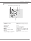
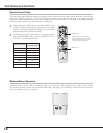
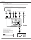
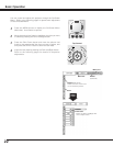
1
DIP
ON
OFF
23 45 6
13" MODE (640 x 480)
16" MODE (832 x 624)
19" MODE (1024 x 768)
OFF
ON
ON
OFF OFF OFF
OFF OFF OFF
OFF OFF OFF
3456
OFF OFFON ON21" MODE (1152 x 870)
ON ON
ON
ON
OFF
OFF
12
ON ON
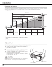
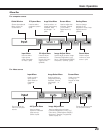
IBM-compatible computer or Macintosh computer (VGA / SVGA / XGA / SXGA)
DVI-VGA Cable
Monitor Output
Desktop type Laptop type
Audio Speaker
(stereo)
Audio Amplifier
Audio Cable
(stereo)
✽
Audio Output
Audio Input
AUDIO OUT
COMPUTER/COMPONENT
AUDIO IN
Cables used for connection (✽ = These accessories are not supplied with this projector.)
Audio
Cable
✽
(stereo)
NOTE :
When connecting the cable, the power
cords of both the projector and the
external equipment should be
disconnected from AC outlet.
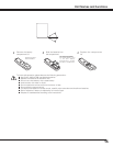
USB port
MAC Adapter ✽
Set slide switch-
es according to
the chart below.
• VGA Cable (HDB 15 pin) ✽
• DVI-VGA Cable (HDB 15 pin)
• DVI-Digital Cable (for Single Link T.M.D.S.) ✽
• USB Cable
• MAC Adapter (When connecting to Macintosh computer)
✽
• Audio Cables ( Mini Plug (stereo) x 2) ✽
External Audio Equipment
Terminals
of the Projector
VGA
Cable
✽
Monitor Output
or
Monitor Input
USB
COMPUTER IN 2 /
COMPONENT IN/
MONITOR OUT
Set switches as shown in the table
below depending on RESOLUTION
MODE that you want to use before
you turn on projector and computer.
◆
MAC ADAPTER (Not supplied)
USB
Cable
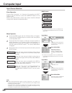
COMPUTER IN 1 DVI-I
DVI Cable ✽
Monitor Output
COMPUTER IN 1 DVI-I
NOTE
● This terminal is switchable. Set the terminal
up as either Computer input or Monitor
output before using this terminal. (See Page
39.)