5
2. WIRING
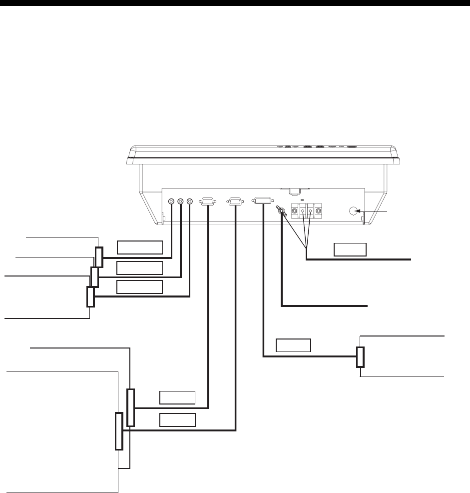
Connect external equipment to the MU-170C by referring to the drawing below, the table on
the next page and the interconnection diagram in this manual.
Note: The MU-170C does not have a “hot plug” function. Therefore, when the power switch
of the MU-170C and the equipment connected to it are on, do not connect or
disconnect the interconnection cable to prevent damage to equipment.
DVI-D
TB-1
RGB1
RGB2
VIDEO1
VIDEO3
VIDEO2
Fuse
( )
(+)
Red
Blue
14AWG-2C-PVC *5M*
(Supplied)
12-24 VDC
Ground terminal
DVI-D/D SINGLELINK5M
(Option)
FAR-21X7 series
CCD camera,
Video cassette
recorder, etc.
2.5C2V or 3C2V
(Local supply)
3COX-2P-6C (Option)
FCV-1200L/1200LM
CH-250
CH-270
CSH-5L/8L
FSV-24/24S
GD-280/380/680
FR-1500 MK3 series
FR-21X5 series
NavNet vx2
Display unit (bottom view)


