


0150-0229D 10 Kalatel DVMRe StoreSafe
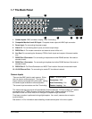
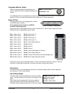
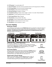
1.7 The Back Panel
B
RS-232/1
AUDIO
12V DC
RS-485/1
10/100
ETHERNET
RS-485/2
RS-232/2
1 2 3 4 5 6 7 8
9 10 11 12 13 14 15 16
1
2
4
5
6
3
7
10
8
9
1. Camera Inputs: BNC connector, looping. Auto Terminating.
2. Composite Monitor-A and -B Output: Composite video output with BNC style connector.
3. Power Input: For connecting the power supply.
4. Alarm I/O: For connecting alarm inputs, and alarm output relays.
5. RS232 Port 1: For modem connection and external control of the unit.
6. Aux Port: For connecting the Accessory PCB for Audio inputs and outputs. Advanced models
only.
7. RS485 Port 2 Connector: For connecting to keyboard and other RS485 devices. Not used on
standard model.
8. RS485 Port 1 Connector: For connecting to keyboard and other RS485 devices. Not used on
standard model.
9. RS232 Port 2: For Event Generation and ASCII Text insertion. Not used on standard model.
10. 10/100 Ethernet Port: For connecting to remote PC via ethernet network.
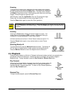
Camera Inputs
Cable: 75-Ohm Coaxial
Connectors: BNC
Auto Terminating: Yes
Passive Looping: Yes
There are two BNC jacks for each camera. Either
jack can receive a camera signal. The signal is
looped (directly connected to the other jack), making
the camera signal available to other equipment.
The camera input connectors are Auto Terminating.
This means that the input signal will automatically be terminated with 75-Ohms unless a 2
nd
cable is
connected to the 2
nd
BNC connector of the same camera input. Make sure there is 75-Ohm
termination at the end of the video line if the signal is looped through StoreSafe.
Time base correction is performed during digital capture. As a result, cameras do not require
synchronization.
See section 3.13 for information about disabling unused camera jacks in the menu system.