


0150-0229D 13 Kalatel DVMRe StoreSafe
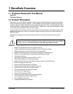
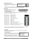
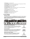
RJ-45 Pin Configuration For Ethernet Port
Pin Use
Pin Use
1 TX+ 5 Not Connected
2 TX- 6 RX-
3 RX+ 7 Not Connected
4 Not Connected 8 Not Connected
82 3 4 5 6 71
RJ-45 socket on back
panel.
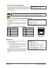
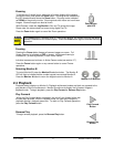
RS232 Port 1
For a Modem connection or remote control of unit. See section 3.16 for information about configuring
the modem settings in the menu system. See section 9 for RS232 Remote Control Protocols.
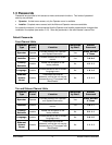
DB-9 Pin Configuration For Port 1
Pin Use
Pin Use
Pin Use
1 DCD 4 DTR 7 RTS
2 RX 5 Ground 8 CTS
3 TX 6 Not Connected 9 Not Connected
1
5
6
9
DB-9 on back panel.
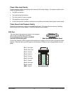
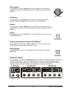
RS232 Port 2 (StoreSafe Advanced Models Only)
For Event Generation and ASCII Text Insertion.
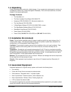
RJ-45 Pin Configuration For RS232 Port 2
Pin Use
Pin Use
1 Ground 5 TXD
2 Reserved 6 Not Connected
3 Not Connected 7 Ground
4 RXD 8 Reserved
82 3 4 5 6 71
RJ-45 socket on
back panel.
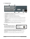
1.8 Power-Up
It is important that the power-up procedures be followed carefully. The unit uses its auto-detect
feature to detect camera signals during power-up, and configure itself automatically.
Power-up procedure
Power Supply Input
Once the system installation is complete, apply
power in the following order:
1. Energize the monitors and all of the cameras.
2. Energize StoreSafe.
Voltage: 12 Volt DC
Power: 60 Watt (5 Amp)
Connector: 2.1mm barrel, center positive
Once power is applied to the unit, it will begin its power-up procedure. The unit will begin by displaying
the software version on Monitor-A, and then the unit will be ready for operation.