


Instructions
Connector Installation
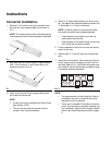
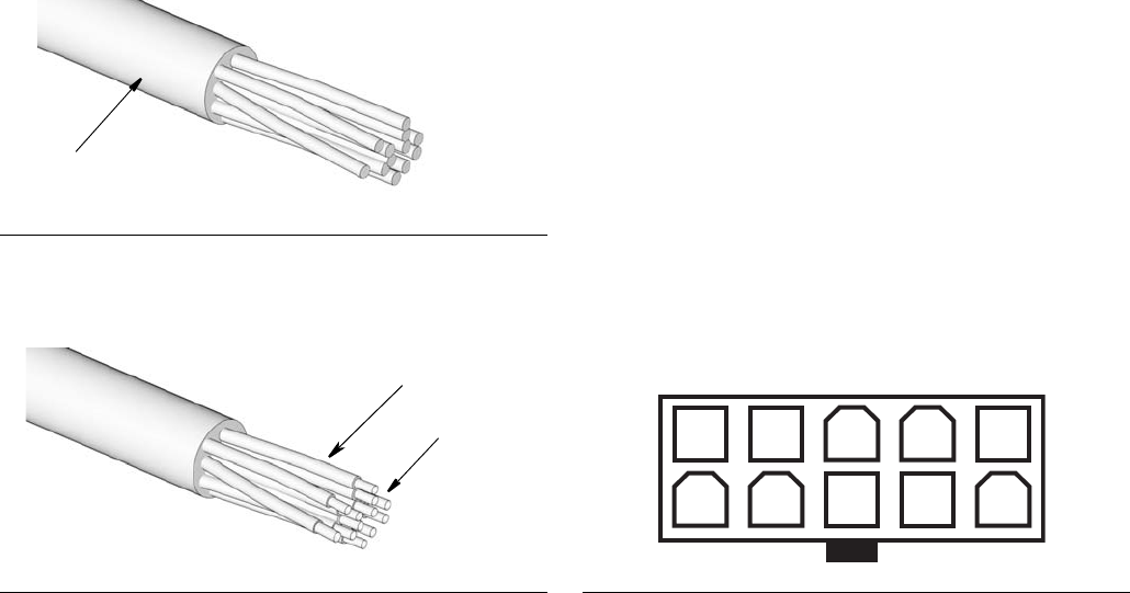
1. Remove 2 to 3 inches of the outer insulation from
one end of a user supplied cable (a) as shown in
F
IG. 1.
NOTE: The cable should contain multicolored wires
to ensure easy and accurate component installation.
.
2. Strip each wire (b) to be crimped so approximately
0.08 - 0.012 inches (2- 3 mm) of bare wire (c) is
showing as shown in F
IG. 2.
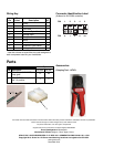
3. Insert one of the pins into the appropriately sized
slot of the hand crimp tool.
NOTE:
• A hand crimp tool is available from Graco. Order
part number 16T671.
• The pin must be placed all the way into the
crimper in the correct orientation.
4. (See F
IG. 2) Insert stripped end (c) of wire (b) into
pin. The edge of the insulation should be about 0.05
- 0.09 inches (1.2- 2.2 mm) into the pin.
NOTE: To ensure proper fit, ensure that the bare
wire and the insulator are crimped separately.
• If the insulation is too deep, the pin will not
make contact with the wire.
• If the insulation is not deep enough, the pin may
not fit inside the connector properly.
5. Firmly squeeze the crimp tool to crimp and secure
the pin to the wire.
6. Repeat steps 3 - 5 until all wires are crimped with
pins.
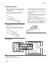
7. Insert pins into connector. When looking at the con-
nector, be sure you are plugging in pins in the cor-
rect side. Refer to F
IG. 3 for correct orientation and
pin locations. Use the Wiring Key provided on page
4 to identify related components.
NOTE:
• The second column of the Wiring Key Table is
provided for the user to record the wire color
assigned to each component.
• There are 10 available PIN locations in the con-
nector. Only use the pin locations necessary for
your installation. Refer to the Connector Identifi-
cation Label and Wiring Key provided on page
4.
FIG. 1
FIG. 2
a
b
c
FIG. 3
5 4 3 2 1
9 8 7 610