


Instructions
3A2992B 3
Component Wiring
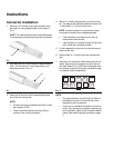
1. Before connecting wires to components verify the
Connector end of the cable is NOT plugged into the
GLC2200 controller.
2. Remove 2 to 3 inches of the outer insulation (a)
from bare end of the cable as shown F
IG. 4.
.
3. Strip each wire (b) you are using for the installation
as shown in F
IG. 5.
NOTE: It is not necessary to strip all of the wires;
only strip the wires needed for your installation.
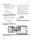
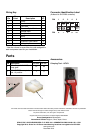
4. Using the Wiring Key Table, connect components to
wires matching each wire color and pin location.
Verify all negative and positive wire colors are cor-
rectly assigned.
NOTE: The second column of the Wiring Key Table
is provided for the user to record the wire color
assigned to each component.
5. Plug connector into the GLC2200 unit matching pin
numbers to Connector Identification Label.
NOTE: The connector can only be plugged into the
GLC2200 one way. The clip (c) should be facing
down when the connector is correctly oriented.
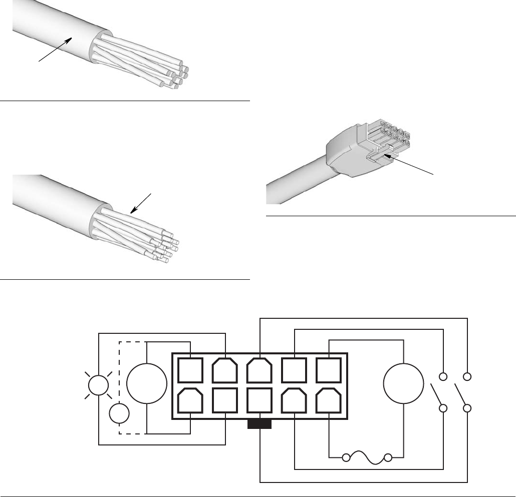
Wiring Diagram
M = Motor pump power or solenoid
V = Electric vent valve for injector-based systems
FIG. 4
FIG. 5
a
b
FIG. 6
c
FIG. 7
1 2 3 4 5
6 7 8 9 10
M
9A Fuse
+
-
V