22
11
11
YY
PbPb
PrPr
LL
RR
LL LL
RR RR
VIDEOVIDEO VIDEOVIDEO
S-VIDEOS-VIDEO
VGAVGA
VGA AUDIOVGA AUDIO
AUDIOAUDIO AUDIOAUDIO
LL
RR
DVI AUDIODVI AUDIO
AUDIOAUDIO
22
LL
RR
AUDIOAUDIO
COMPONENT INCOMPONENT IN
VIDEO INVIDEO IN
11
AV OUTAV OUT
VGA INVGA IN
HDMI INHDMI IN
ANT INANT IN
OPTICAL OUTOPTICAL OUT
Back panel controls
Introduction
Owner s Manual 7
Connection Options
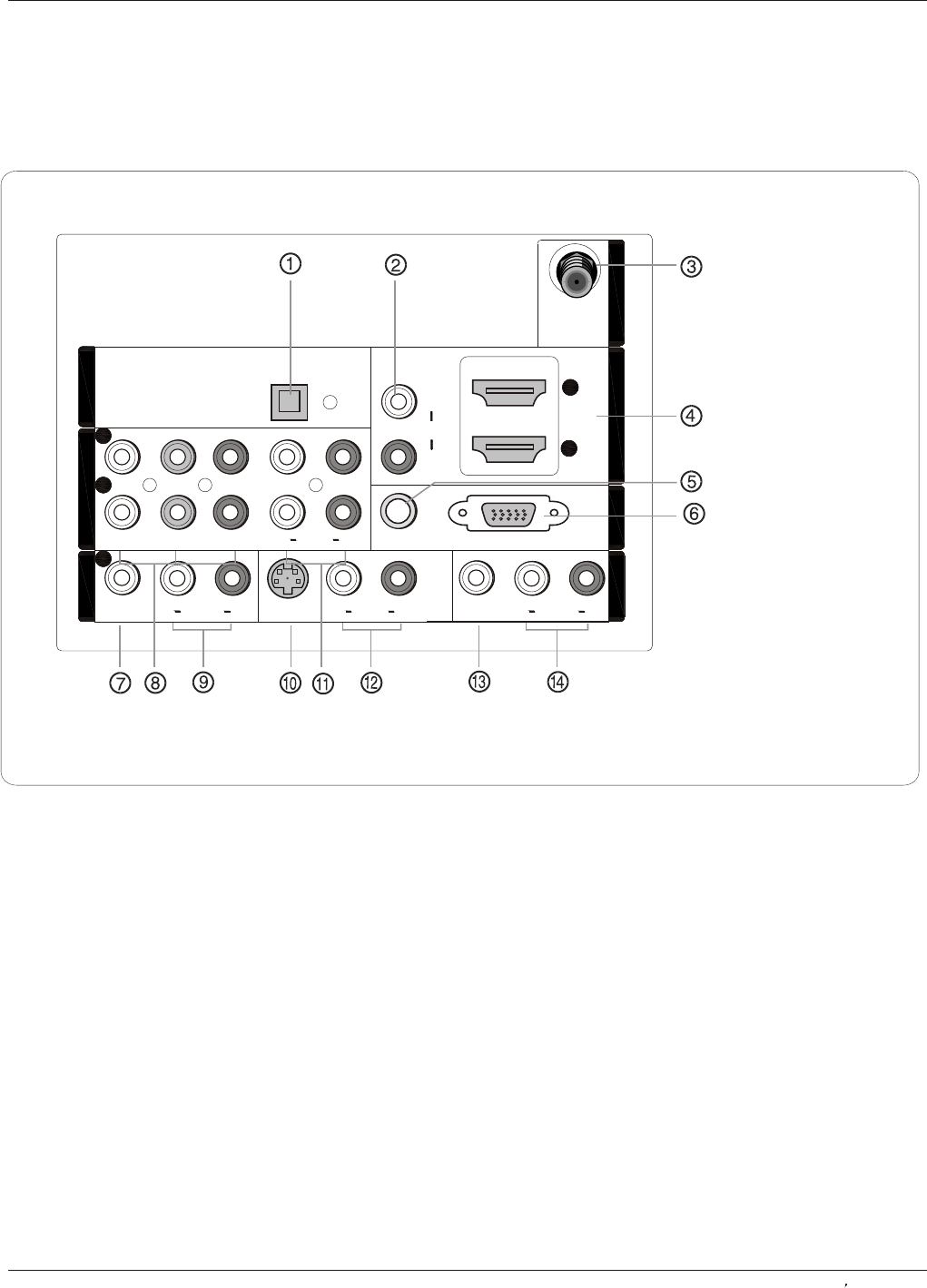
1. Digital Audio Output: Connect digital audio from various types of equipment.
NOTE: In standby mode, these ports will not work.
2. DVI Audio In: Connect a component video device to these jacks.
3. Antenna Input: Connect cable or antenna signals to the TV, either directly or through your cable box.
4. HDMI In: Connect a signal to HDMI.
5.VGA Audio In: Connect the audio L/R cables from a computer to this jack.
6.VGA Video In: Connect a video cable from a computer to this jack.
7. VIDEO In: Connects the video signal from a video device.
8. DVD/DTV In(Component ): Connect a component video device to these jacks.
9. AUDIO In: Connect to hear stereo sound from an external device.
10. S-VIDEO In: Connect S-Video out from an S-VIDEO device to the S-VIDEO input.
11. COMPONENT AUDIO In: Connect to hear stereo sound from an external device.
12. AUDIO In: Connect to hear stereo sound from an external device.
13. VIDEO Out: Connect the second TV or monitor to the TV`s AV OUT.
14. AUDIO Out: Connect to the left and right audio input jacks of your audio or video equipment.


