


5
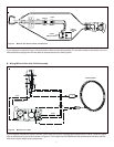
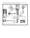
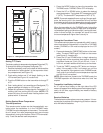
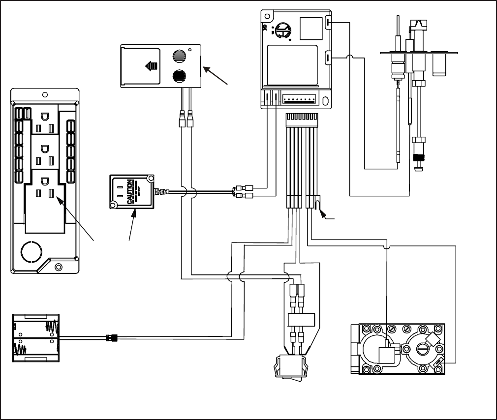
Figure 8. Intermittent Pilot Ignition (IPI) Wiring Diagram
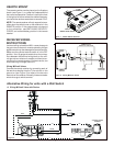
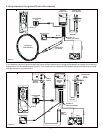
If your fireplace look like Figure 7 find the leads on the back of switch marked “For use with remote or wall switch only”.
Take the leads and plus them into wire leads on remote receiver box (see Figure 8).
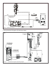
ON/OFF
SLIDE
SWITCH
BLACK
RED
BATTERY PACK
PIGGYBACK
ON/OFF SWITCH
GRN
ORG
BROWN
BROWN
ORANGE
WHITE
TRANSFORMER
3 VAC
PLUG IN
GROUND TO
FIREPLACE CHASSIS
INTERMITTENT
PILOT
IGNITOR
IGNITION
MODULE
3 VAC
VALVE
For use with
remote or
wall switch only
1 2 3
NEUTRAL
HOT
5 4 3 2 1
5 4 3 2 1
TRANS
REM/AUX
FAN
I
S
LEARN
REMOTE
RECEIVER
WIRE
TERMINAL