


2 Installing the Cable Management Bracket
Figure 2-1 shows the correct orientation of the cable management bracket that you must install
before connecting the cables to the InfiniBand switch. The bracket provides strain relief for the
InfiniBand ports, and maintains the correct minimum cable bend radius.
Note:
One cable management kit is required for each InfiniBand switch.
2.1 Installing the Cable Management Bracket
To install the cable management bracket, follow these steps:
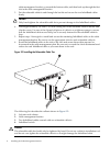
1. Align the cable management bracket (callout 2 in Figure 2-1) in the same “U” location as the
InfiniBand switch.
Note:
The location of the cable management bracket depends on the rack position occupied by the
InfiniBand switch.
2. Using the top hole in the same “U” location as the InfiniBand switch, fasten the cable
management bracket (callout 2 in Figure 2-1) to the rear rack columns (callout 1 in Figure 2-1)
by using two M6 pan-head screws (callout 3 in Figure 2-1) and tighten them to the specified
torque (see Table 1-1).
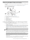
Figure 2-1 Mounting the Cable Management Bracket
1
2
3
2.2 Installing the Releasable Cable Ties to Secure the InfiniBand Cables
To install the InfiniBand cables and secure them with the releasable cable ties, follow these steps:
Note:
For instructions on how to install cables in the InfiniBand switch or remove cables from the
InfiniBand switch, read the installation guide for the InfiniBand switch type that you installed.
1. Looking in from the rear of the rack, install one InfiniBand cable in the top left port and the
other cable in the bottom left port of the InfiniBand switch (see Figure 2-2).
2. Secure two of the InfiniBand cables at a time (callout 3 in Figure 2-2) to the cable management
bracket by sliding the releasable cable tie down through the second slot from the left on the
2.1 Installing the Cable Management Bracket 7