


17
English
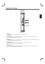
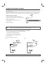
⑨
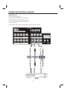
L/ MONO / R (VIDEO 3)
Connect audio of external devices.(if you have mono sound, insert the audio cable into the left (L) audio jack).
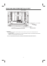
⑩
ANALOG RGB INPUT
Use this 15-pin D-Sub input for your external devices with RGB output using the D-Sub Mini 15-pin cable provided.
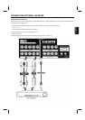
⑪
ANALOG RGB / HDMI AUDIO IN
Connect audio for ANALOG RGB and HDMI input.
⑫
SUBWOOFER Output
Connect this SUB WOOFER OUT output to the external audio component input.
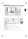
⑬
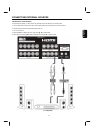
AUDIO Output
These jacks provide fixed audio signal which are used for recording.
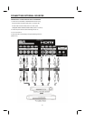
⑭
MONITOR Output (S VIDEO)
This jack provides S video signal which are used for recording. (Please refer to monitor output table as below)
⑮
MONITOR Output (VIDEO)
This jack provides video and audio signals which are used for recording. (Please refer to monitor output table as below)
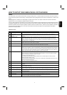
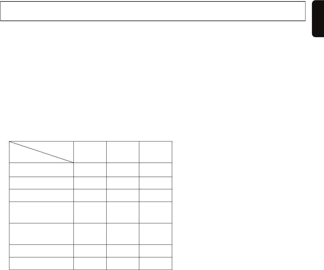
Monitor output table:
(a) Normal mode:
Output
Input
S-VIDEO VIDEO AUDIO
DTV
○ ○ ○
NTSC
× ○ ○
VIDEO1/ VIDEO2
× × ×
VIDEO3/ VIDEO4
(VIDEO)
× ○ ○
VIDEO3/ VIDEO4
(S-VIDEO)
○ × ○
ANALOG RGB
× × ×
HDMI
× × ×
(b) For POP/PIP mode:
The monitor output is according to user‘s selected source, the speaker’s position.
The output table should be the same with the above table.
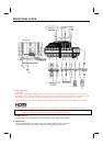
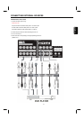
⑯
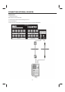
L/MONO /R (VIDEO 1 and VIDEO 2)
Connect audio of external devices.(if you have mono sound, insert the audio cable into the left (L) audio jack).
⑰
Y-PBPR (VIDEO 1 and VIDEO 2)
Provide Y-P
BPR jacks for connecting equipment with this capability, such as a DVD player or Set Top Box
⑱
NTSC TUNER
RF input that connects to the antenna, cable box, or CATV cable. Support NTSC TV system.
⑲
DTV TUNER
RF input that connects to the antenna, cable box, or CATV cable. Support ATSC TV system.
NOTES: In case of using analog audio, when connecting with DVI-HDMI transformation connector, use ANALOG
RGB / HDMI audio terminal for in
p
ut.