


19
Connecting External Video Sources
First time use
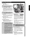
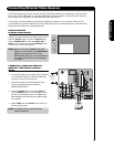
Your HITACHI LCD Rear Projection Television is equipped with an AV Network feature. This feature helps to
control your external Audio/Video equipment (VCR, Set Top Box, DVD, etc.). Once this is setup, it allows
your IR Mouse connector to control your equipment using your HITACHI LCD Rear PTV Remote Control.
You can use your HITACHI remote control to control the Audio/Video equipment command without the
equipment’s remote control.
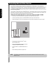
The LCD Rear PTV Rear Panel has 2 IR BLASTER jacks. Each IR Mouse cable can connect up to 2
external Audio/Video components. Therefore, you can connect the LCD Rear PTV with up to four
components. Please see the following example of an AV Network setup between your HITACHI LCD Rear
PTV and external Audio/Video equipment (VCR and DVD Player).
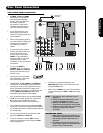
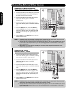
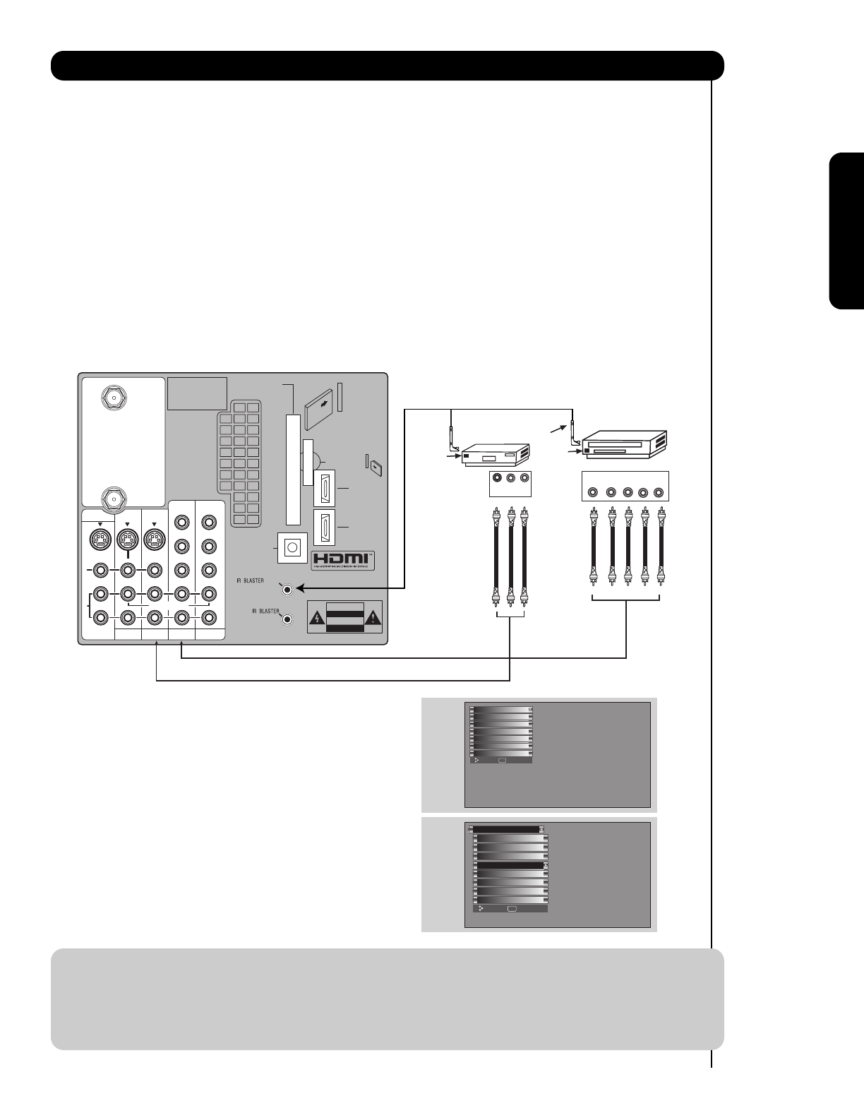
CONNECTING EXTERNAL AUDIO/VIDEO COMPONENTS TO IR BLASTER FOR AV NETWORK
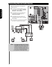
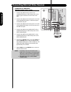
1. Connect your external Audio/Video components to the Rear Panel shown below.
2. Connect the IR Mouse cable to the IR BLASTER output of the Rear Panel.
3. Place the IR Mouse in front of the infrared sensor of the external components you wish to control.
NOTE: 1. The Rear Panel has two IR BLASTER outputs which can control up to a total of four external
components.
2. The IR Mouse must be placed in front of the external components infrared sensor for the AV
Network to work. Double-sided mounting tape may be used to hold the IR Mouse in place.
3. The correct codes must be chosen for each of the Audio/Video components for the AV Network to
function properly.
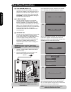
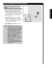
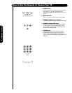
4. ACCESS THE AV NET SETUP WIZARD
Press the MENU button.
5. Use the CURSOR PAD ̄ or channel scroll down
to highlight SETUP.
6. Press the SELECT or CURSOR PAD ̈ button to
select.
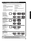
7. Use the CURSOR PAD ̄ or channel scroll to
highlight the SET AV NET features then press the
SELECT button.
8. Follow the Setup procedure on pages 76-83.
R
L
A
U
D
I
O
V
I
D
E
O
S
I
V
I
D
E
O
(MONO)(MONO)(MONO)(MONO)
P
R
P
B
Y/
VIDEO
Y/
VIDEO
P
R
P
B
P
R
P
B
P
R
P
B
MONITOR OUT
AUDIO
TO HI-FI
INPUT 1
CABLE
AIR
INPUT 2
TV AS CENTER
INPUT 3 INPUT 4
CableCARD™
CAUTION
(Top of card faces right)
Top faces
OPTICAL OUT
Digital Audio
Upgrade Card
HDMI INPUT 1
HDMI INPUT 2
Apparatus Claims of U.S.
Patent Nos. 4,631,603;
4,577,216; 4,819,098;
4,907,093; and 6,381,747
licensed for limited
viewing uses only.
G-LINK
/
DVD Player
V L R
OUTPUT
VCR
Infrared
Sensor
Infrared
Sensor
IR
Mouse
OUTPUT
YP
B
/C
B
P
R
/C
R
R L
Move SEL Select
Setup
Timers
Locks
TV Guide On Screen
Channel Manager
Audio
Video
Menu Preference
Set AV NET
Set Closed Captions
Set The Inputs
Upgrades
Set Monitor Out
Quick Start Up
Setup
Move SEL Set
Lamp Power Control