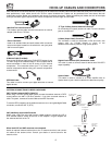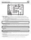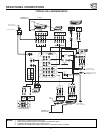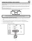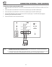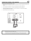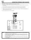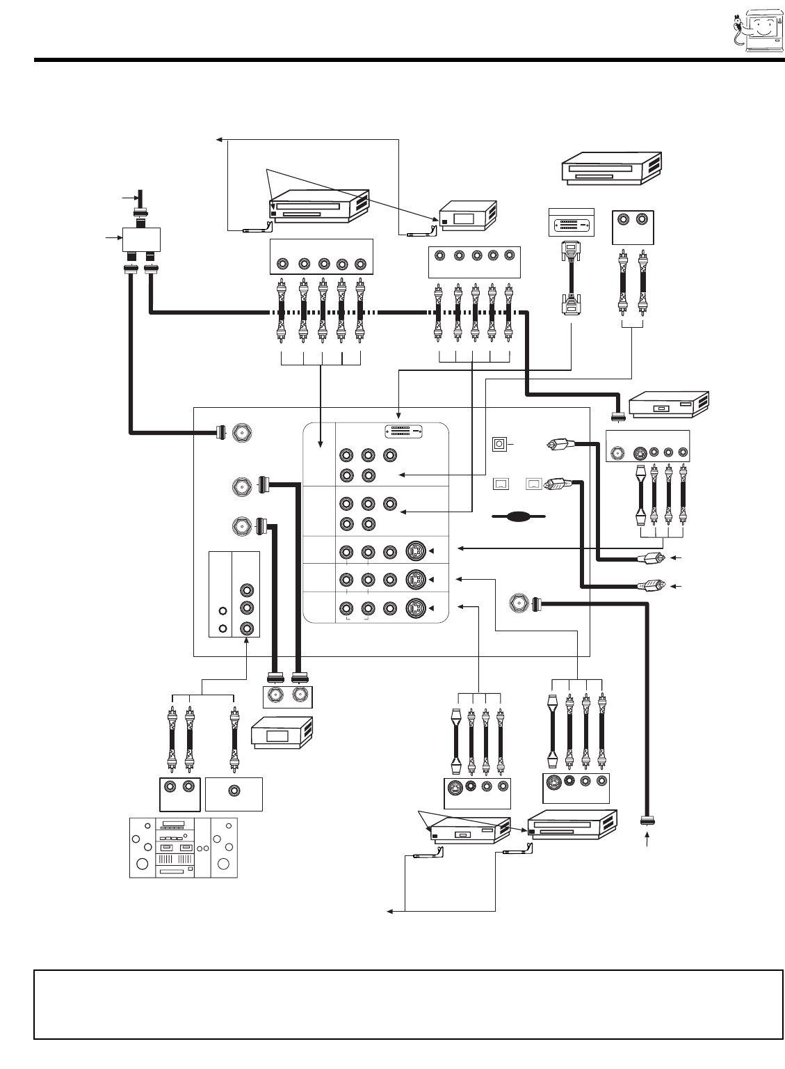
REAR PANEL CONNECTIONS
11
NOTES: 1.
Connect only 1 component to each input jack.
2. Follow connections that pertain to your personal entertainment system.
3. Composite video signal can be input to Input2~Input5.
4. Cables are not included with the purchase of this TV, except when noted as “provided”.
TYPICAL FULL-FEATURE SETUP
Outside antenna or
cable TV coaxial cable
2-Way signal splitter
Stereo System Amplifier
Laserdisc player, VCR,
camcorder, etc.
HDTV Set-Top Box
DVD Player
Cable TV Box
VCR #1
ANT
IN
OUTPUT
S-VIDEO
VLR
(Provided)
(Provided)
D-VHS
DIGITAL OUTPUT
LR
OUTPUT
OUTPUT
YP
B
/C
B
P
R
/C
R
L R
VCR #2
V L R
OUTPUT
S-VIDEO
V L R
INPUT
S-VIDEO
OUTPUT
Y P
B
P
R
L R
CONNECT TO
IR BLASTER
CONNECT TO
IR BLASTER
IR
Sensor
IR
Sensor
P
B
P
R
CENTER
IN
P
B
P
R
DVI-HDTV
Outside antenna or
cable TV coaxial cable
To an amplifier/receiver
with optical input capability.
To a digital IEEE1394 capable
device, such as a Digital VCR
or Set-Top-Box.
CENTER OUTPUT
LR
INPUT
ANT A
TO
CONVERTER
ANT B
L
Y
R
(MONO)/L
IR
BLASTER
AUDIO
TO HI-FI
R
S-VIDEO
S-VIDEO
S-VIDEO
Y/VIDEO
R
(MONO)/L
R
(MONO)/L VIDEO
R
(MONO)/L VIDEO
R
LVIDEO
INPUT 1
INPUT 2
INPUT 3
INPUT 4
MONITOR
OUT
AUDIO
AUDIO
AUDIO
ANT C
(DTV)
Multi Media Card
IEEE1394
OPTICAL OUT
Digital Audio
OUTPUT
INPUT


