


13
First time use
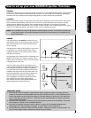
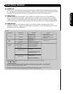
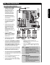
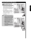
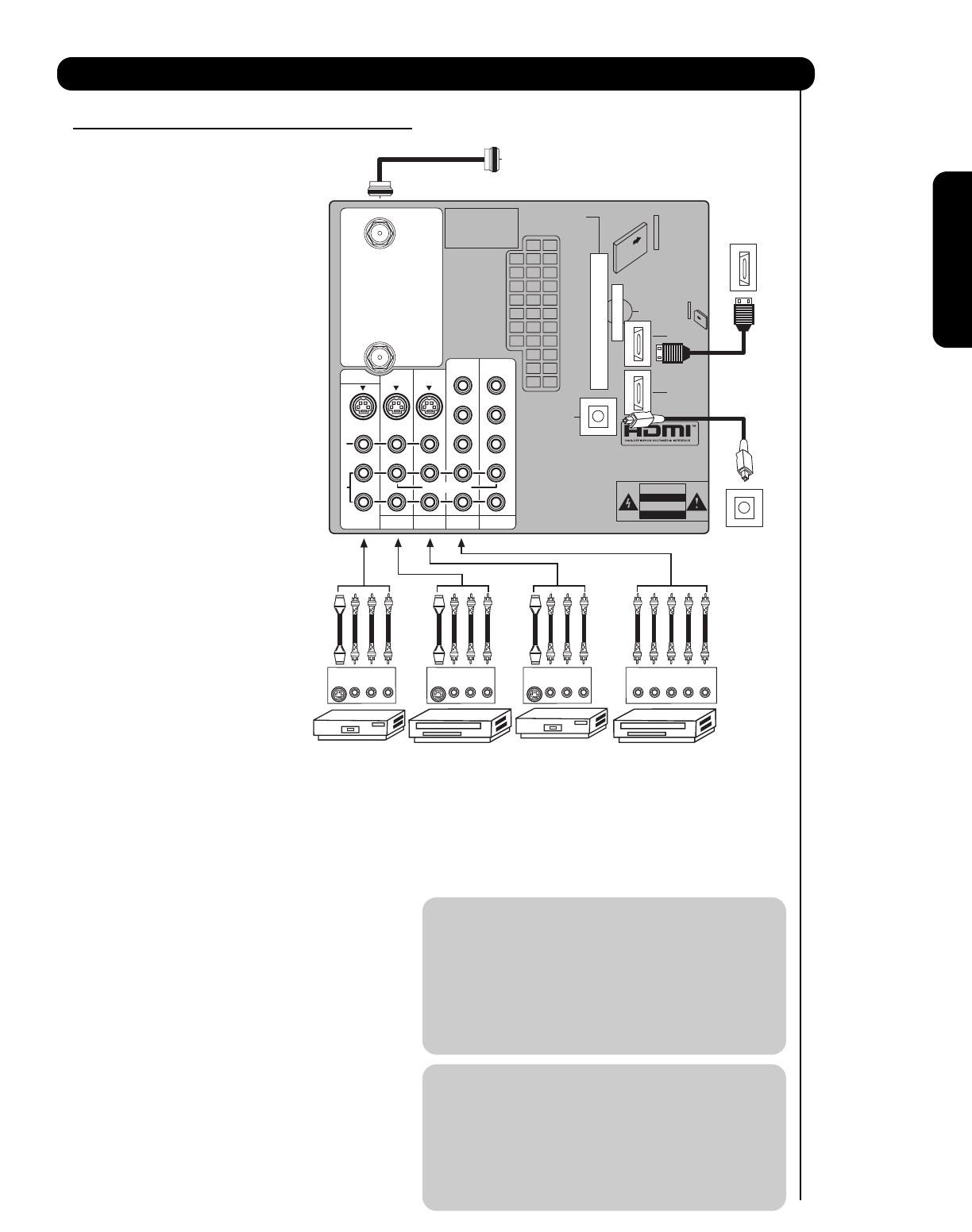
TIPS ON REAR PANEL CONNECTIONS
• S-VIDEO, Y- P
BPR and HDMI
connections are provided for
high performance laserdisc
players, VCRs etc. that have
this feature. Use these
connections in place of the
standard video connection if
your device has this feature.
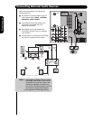
• If your device has only one
audio output (mono sound),
connect it to the left audio jack
on the television.
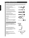
• Refer to the operating guide of
your other electronic equipment
for additional information on
connecting your hook-up
cables.
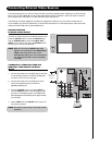
• A single VCR can be used for
VCR #1 and VCR #2, but note
that a VCR cannot record
its own video or line output
(INPUT 1 in the example on
this page). Refer to your VCR
operating guide for more
information on line input-output
connections.
• You may use VIDEO or
S-VIDEO inputs to connect to
INPUT 1, INPUT 2 or INPUT 5,
but only one of these may be
used at a time.
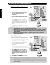
• Connect only one component
(VCR, DVD player, camcorder,
etc.) to each input jack.
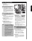
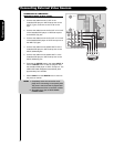
• COMPONENT: Y- P
BPR (INPUT 3 and INPUT 4)
connections are provided for high performance
components, such as DVD players and set-top-
boxes. Use these connections in place of the
standard video connection if your device has this
feature. INPUT 3 and INPUT 4 accepts both
composite and component video signals.
• Your component outputs may be labeled Y, B-Y,
and R-Y. In this case, connect the components
B-Y output to the TV’s P
B input and the
components R-Y output to the TV’s P
R input.
• Your component outputs may be labeled Y-C
BCR.
In this case, connect the components C
B output to
the TV’s P
B input and the components CR output to
the TV’s P
R input.
• You may use composite and component video
signals for INPUT 3 and INPUT 4.
• It may be necessary to adjust TINT to obtain
optimum picture quality when using the Y-P
BPR
inputs (see page 33).
• To ensure no copyright infringement, the
MONITOR OUT output may be abnormal, when
using the Y-P
BPR jacks.
• When using an HDMI input from a Set-Top-Box, it
is recommended that a 1080i or 720p input signal
is used.
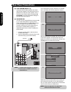
NOTE: 1. Connect only one component to each
input jack.
2. Follow connections that pertain to your
personal entertainment system.
3. INPUT 3 and INPUT 4 can accomodate
Composite and Component video signals.
4. Cables are not included with the purchase
of this TV, except when noted as
“provided”.
MACROVISION NOTES:
1. Video signals fed through a VCR may be
affected by copyright protection systems
and the picture will be distorted on the
television.
2. Connecting the television directly to the
Audio /Video output of a Set-Top-Box will
assure a more normal picture.
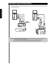
Rear Panel Connections
R
L
A
U
D
I
O
V
I
D
E
O
S
I
V
I
D
E
O
(MONO)(MONO)(MONO)(MONO)
P
R
P
B
Y/
VIDEO
Y/
VIDEO
P
R
P
B
P
R
P
B
P
R
P
B
MONITOR OUT
AUDIO
TO HI-FI
INPUT 1
CABLE
AIR
INPUT 2
TV AS CENTER
INPUT 3 INPUT 4
CableCARD™
CAUTION
(Top of card faces right)
Top faces
OPTICAL OUT
Digital Audio
Upgrade Card
HDMI INPUT 1
Apparatus Claims of U.S.
Patent Nos. 4,631,603;
4,577,216; 4,819,098;
4,907,093; and 6,381,747
licensed for limited
viewing uses only.
Outside Antenna
or Digital Cable
Laserdisc player, VCR,
Camcorder, etc.
VCR #2 VCR #1 DVD Player
To an
amplifier/
receiver with
optical input
capability.
External
Digital
Component
with HDMI
output
capability
INPUT
S-VIDEO
VL R
OUTPUT
S-VIDEO
VL R
OUTPUT
RLPB/CB PR/CRY
OUTPUT
S-VIDEO
VL R
HDMI OUT
OPTICAL IN
HDMI INPUT 2