


15
Connecting External Video Sources
First time use
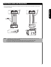
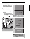
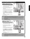
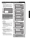
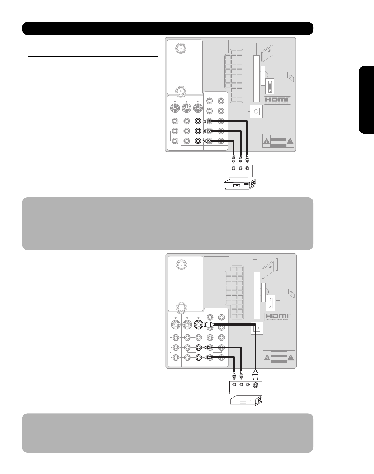
CONNECTING A COMPOSITE VIDEO AND A
STEREO AUDIO SOURCE TO INPUT1 – INPUT5
1. Connect the cable from the VIDEO OUT of the VCR
or the laserdisc player to the INPUT (VIDEO) jack,
as shown on the TV to the right.
2. Connect the cable from the AUDIO OUT R of the
VCR or the laserdisc player to the INPUT
(AUDIO/R) jack.
3. Connect the cable from the AUDIO OUT L of the VCR
or the laserdisc player to the INPUT (AUDIO/L) jack.
4. Press the INPUTS button, then select INPUT 2
from the INPUTS menu to view the program from
the VCR or laserdisc player. The VIDEO OSD label
disappears automatically after approximately four
seconds.
5. Select CABLE from the INPUTS menu to return to
the last channel tuned.
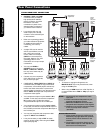
NOTE: 1. Completely insert the connection cord plugs when connecting to rear panel jacks. The picture and
sound that is played back will be abnormal if the connection is loose.
2. A single VCR can be used for VCR #1 and VCR #2 (see page 12), but note that a VCR cannot record
its own video or line output. Refer to your VCR operating guide for more information on line input-
output connections.
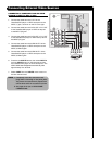
3. When INPUT 3 or 4 are used, it is necessary to connect the video output from the device to the
Y-VIDEO INPUT jack of the TV.
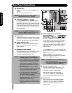
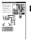
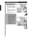
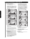
CONNECTING AN S-VIDEO AND STEREO
SOURCE TO INPUT 1, 2 AND 5
1. Connect the cable from the S-VIDEO OUT of the
VCR or the laserdisc player to the INPUT (S-VIDEO)
jack, as shown on the TV to the right.
2. Connect the cable from the AUDIO OUT R of the
VCR or the laserdisc player to the INPUT
(AUDIO/R) jack.
3. Connect the cable from the AUDIO OUT L of the VCR
or the laserdisc player to the INPUT (AUDIO/L) jack.
4. Press the INPUTS button, then select INPUT 2
from the INPUTS menu to view the program from
the VCR or laserdisc player. The VIDEO OSD label
disappears automatically after approximately four
seconds.
5. Select CABLE from the INPUTS menu to return to
the last channel tuned.
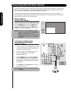
NOTE: 1. Completely insert the connection cord plugs when connecting to rear panel jacks. The picture and
sound that is played back will be abnormal if the connection is loose.
2. A single VCR can be used for VCR #1 and VCR #2 (see page 12), but note that a VCR cannot record
its own video or line output. Refer to your VCR operating guide for more information on line input-
output connections.
R
L
A
U
D
I
O
V
I
D
E
O
S
I
V
I
D
E
O
(MONO)(MONO)(MONO)(MONO)
P
R
P
B
Y/
VIDEO
Y/
VIDEO
P
R
P
B
P
R
P
B
P
R
P
B
MONITOR OUT
AUDIO
TO HI-FI
INPUT 1
CABLE
AIR
INPUT 2
TV AS CENTER
INPUT 3 INPUT 4
CableCARD™
CAUTION
(Top of card faces right)
Top faces
OPTICAL OUT
Digital Audio
Upgrade Card
HDMI INPUT 1
Apparatus Claims of U.S.
Patent Nos. 4,631,603;
4,577,216; 4,819,098;
4,907,093; and 6,381,747
licensed for limited
viewing uses only.
VLR
VCR
OUTPUT
R
L
A
U
D
I
O
V
I
D
E
O
S
I
V
I
D
E
O
(MONO)(MONO)(MONO)(MONO)
P
R
P
B
Y/
VIDEO
Y/
VIDEO
P
R
P
B
P
R
P
B
P
R
P
B
MONITOR OUT
AUDIO
TO HI-FI
INPUT 1
CABLE
AIR
INPUT 2
TV AS CENTER
INPUT 3 INPUT 4
CableCARD™
CAUTION
(Top of card faces right)
Top faces
OPTICAL OUT
Digital Audio
Upgrade Card
HDMI INPUT 1
Apparatus Claims of U.S.
Patent Nos. 4,631,603;
4,577,216; 4,819,098;
4,907,093; and 6,381,747
licensed for limited
viewing uses only.
V
S-VIDEO
LR
VCR
OUTPUT