


58
ASSEMBLY PROCEDURE
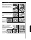
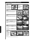
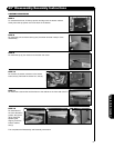
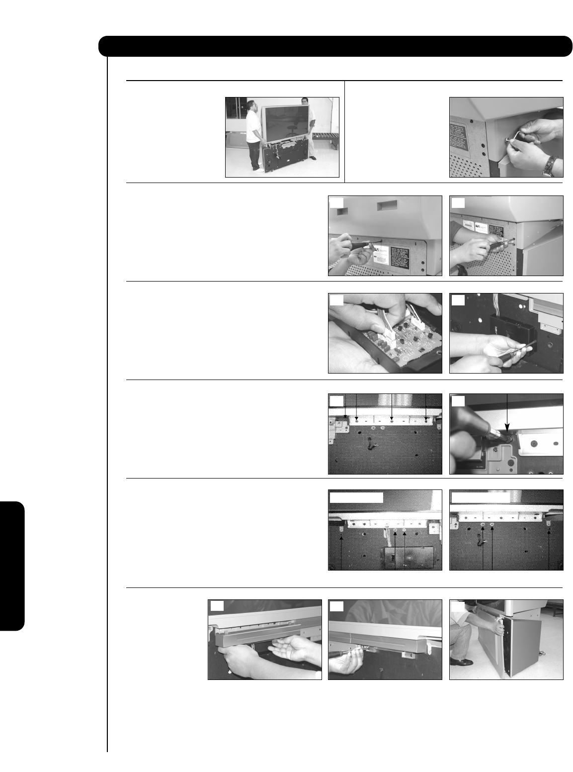
STEP 10
Re-install the top (4) four screws into the lower rear
cover, see (a). Re-install the (4) four side screws that
hold the back cover to the cabinet, see (b).
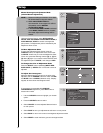
STEP 11
Re-connect the sensor connector to the sensor
board, see (a). Re-install the sensor box, see (b).
STEP 12
Re-install 4 screws (³, ·, », ¿) that hold the
screen frame to the cabinet on the Right side, see
(a) and (b). Repeat to re-install 4 screws on the
Left side.
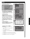
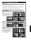
STEP 13
Please re-install 3 screws (³, ·, ») below screen
frame that hold the back cover to the cabinet as the
arrows shows.
Please re-install 3 screws (¿, ´, ²) below screen
frame that hold the back cover to the cabinet as the
arrows shows.
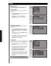
STEP 14
Re-install both of the
front decoration
panels, see (a) and
(b). Re-install the
speaker grille,
aligning it with the
bottom cabinet,
see (c).
This completes the Disassembly and Assembly instructions.
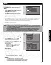
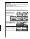
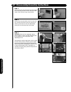
STEP 8
To re-assemble the set,
lift the top portion and
align onto the bottom
cabinet. Gently lower the
top portion until it sits
flush on the bottom.
STEP 9
Re-install the joint
connector bolts (4 pcs.)
that were removed in
step 5 of the
disassembly.
57” Disassembly/Assembly Instructions
(a) (b)
(a)
(b)
(a)
(b)
(c)
¿»·³
(a) (b)
¿
³ ·» ²´ ¿
(a) left side (b) right side
Useful Information