


16
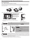
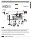
Rear Panel Connections
• Completely insert the connection cord plugs when connecting to rear panel jacks. The picture and sound that is played
back will be abnormal if the connection is loose.
• Cable plugs are often color-coded. Match colors of plugs and terminals, i.e. connect red to red, white to white, etc.
• To return to the last channel viewed, select “0.TV” from the INPUTS menu.
NOTES
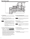
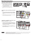
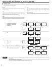
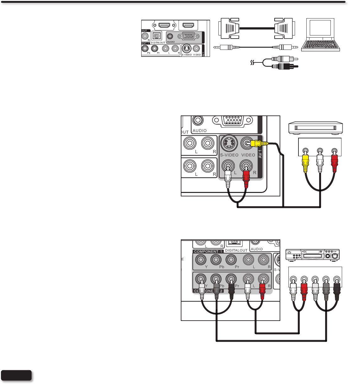
CONNECTING A COMPONENT AND STEREO AUDIO
SOURCE TO COMPONENT 1 or 2: YPbPr
1. Connect the Y, Pb/Cb, Pr/Cr and AUDIO cables from the Y, Pb/
Cb, Pr/Cr OUT and AUDIO OUT jacks of the DVD PLAYER or
HDTV Set-Top-Box to the COMPONENT 1 or 2 YPbPr and
AUDIO jacks. A DVD connection to Rear Panel COMPONENT
2 example is shown on the right.
2. Press the INPUT button, then select COMPONENT 1 or 2
from the INPUTS menu to view the program from the DVD
player or HDTV Set-Top Box.
TV REAR PANEL
de Dolby
Output
L R Y PB PR
White
Red
Green
Blue
Red
DVD Player/ HDTV STB
DVD player
VCR
Home video game system
Camcorder
RGB
RGB
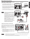
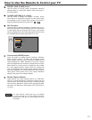
CONNECTING A VIDEO AND STEREO AUDIO SOURCE
TO AV1
1. Connect the VIDEO and AUDIO cables from the VIDEO OUT
and AUDIO OUT jacks of the VCR to the AV1 (VIDEO)jacks.
A VCR connection to Rear Panel AV1 example is shown on
the right.
2. Press the INPUT button, then select AV1 from the INPUTS
menu to view the program from the VCR.
OUTPUT
VIDEO
L R
TV REAR PANEL
(Yellow)
(White)
(Red)
DVD player
VCR
Home video game system
Camcorder
VCR
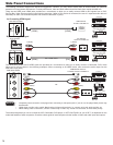
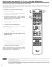
CONNECTING A PERSONAL COMPUTER
Use the RGB PC connection terminal and the
Analog Audio Input terminals to connect the PC.
1. Connect the RGB (D-sub 15 Pin) and AUDIO
cable from the RGB and AUDIO OUT jack of
the PC to the RGB and AUDIO jack, as shown
on the Side Panel on the right.
2. Press the INPUT button, then select RGB from
the INPUTS menu to view the signal from the
PC.
RGB
RGB
IN
(D-sub 15 Pin) or
(Audio)
OUT [PC sample]