


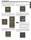
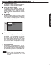
FIRST TIME USE
17
RGB
RGB
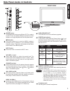
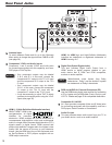
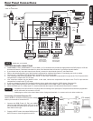
Rear Panel Connections
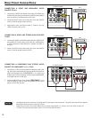
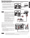
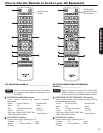
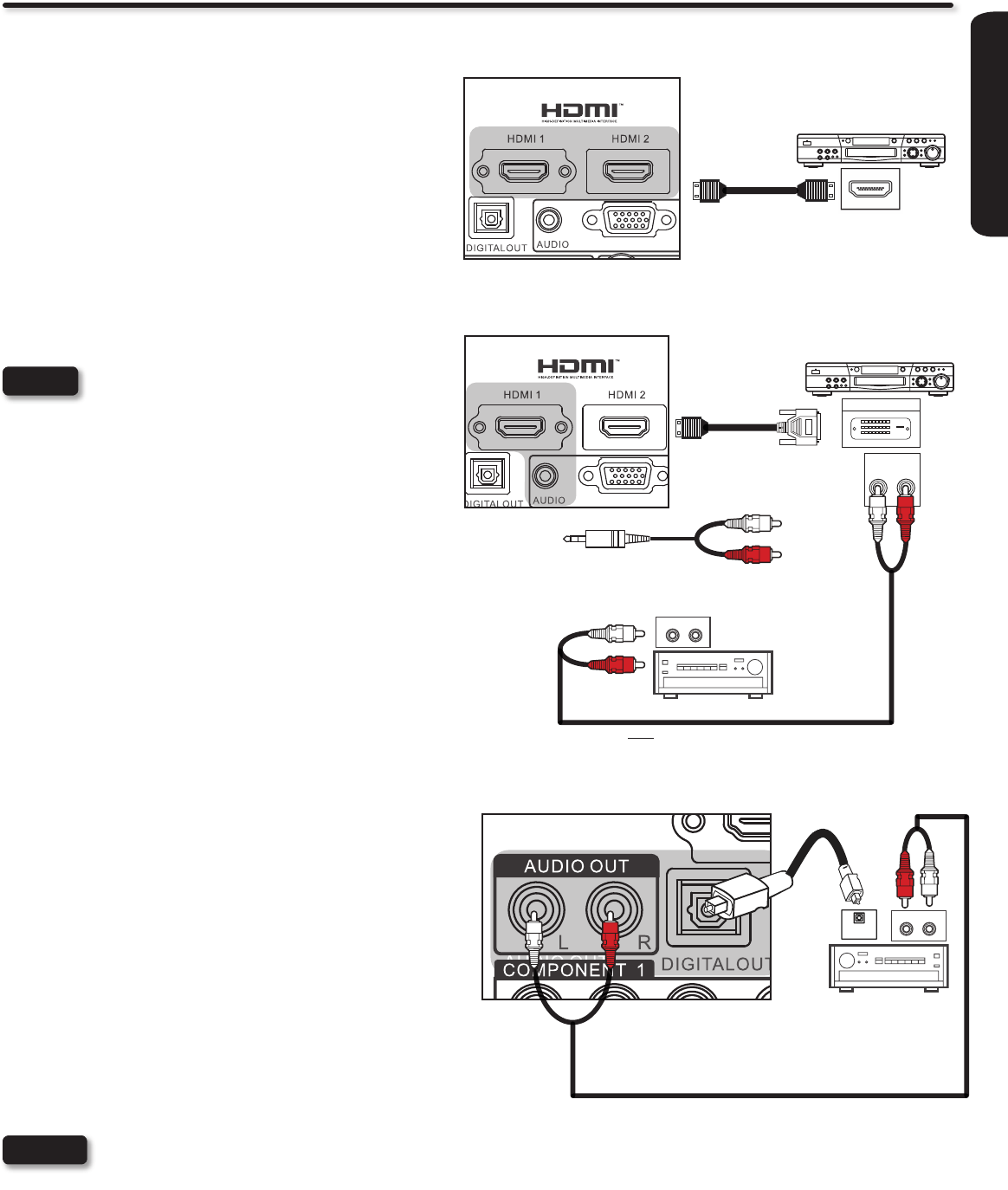
CONNECTING AN EQUIPMENT SOURCE WITH HDMI
OR DVI CAPABILITY TO HDMI 1, HDMI 2
Connect the HDMI or DVI to HDMI connection cable from the 1.
output of the HDTV set top box or DVD player to the HDMI
input as shown near the Rear panel at right.
With DVI output, connect the audio cables from the AUDIO 2.
OUT jack of the HDTV set top box or DVD player to an external
audio amplier as shown to the right below. Optionally you can
use the Audio input from the RGB audio connections when
used with the HDMI1 input.
Press the INPUT button, then select HDMI 1 or 2 to view the 3.
program from the HDTV SET-TOP BOX or DVD player.
Completely insert the connection cord plugs when •
connecting to the rear panel jacks. The picture and
sound that is played back will be abnormal if the
connection is loose.
When using a DVI to HDMI cable, connect the Audio •
Out L and R cables to an external audio amplier.
The HDMI input on HDMI 1, 2, 3 and 4 contains •
the copy protection system called High-bandwidth
Digital Content Protection (HDCP). HDCP is a
cryptographic system that encrypts video signals
when using HDMI connections to prevent illegal
copying of video contents.
HDMI is not a “NETWORK” technology. It establishes •
a one-way, point-to-point connection for delivery of
uncompressed video to a display.
The connected digital output device controls the •
HDMI interface, so proper set-up of device user
settings determines nal video appearance.
Only HDMI1 can support DVI audio input when it is •
connected to the RGB audio input terminal.
NOTES
HDMI OUT
[HDMI] [HDMI]
HDMI DIGITAL
OUTPUT CAPABILITY
TV REAR PANEL
HDMI Input
DVI to HDMI Input
DIGITAL OUTPUT
DVI DIGITAL
OUTPUT CAPABILITY
TV REAR PANEL
Audio Output
L R
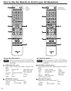
CONNECTING AN EXTERNAL AUDIO AMPLIFIER
To monitor the audio level of the LCD TV to an external audio
amplier, connect the system as shown on the right. The “OPTICAL
OUT” and “AUDIO OUT” from the Rear Panel is a xed output. The
Volume of the amplier is controlled by the amplier, not by the
LCD Television.
The OPTICAL OUT terminal outputs all audio sources to equipment
with Optical IN capability.
Connect an optical cable from the OPTICAL OUT to the 1.
OPTICAL IN of a separate Stereo System Amplier as shown
on the Rear Panel on the right.
Connect an RCA stereo cable from the AUDIO OUT to the 2.
Audio input of a separate Stereo System Amplier as shown
on the Rear Panel on the right.
Completely insert the connection cord plugs when connecting to rear panel jacks. The picture and sound that is played •
back will be abnormal if the connection is loose.
Cable plugs are often color-coded. Match colors of plugs and terminals, i.e. connect red to red, white to white, etc.•
To return to the last channel viewed, select “0.TV” from the INPUTS menu.•
NOTES
TV REAR PANEL
OPTICAL
IN
STEREO SYSTEM
AMPLIFIER
Optical cable
(Red)
(White)
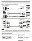
DVD Player/ Recorder
DVD Player/ Recorder
DVD player
VCR
Home video game system
Camcorder
RGB
RGB
Manufactured under license from Dolby Laboratories. "Dolby" and
the double-D symbol are trademarks of Dolby Laboratories.
Fabriqué sous licence de Dolby Laboratories. Le terme « Dolby »
et le sigle double D sont des marques commerciales de Dolby
Laboratories.
TruSurround HD, SRS and
symbol are trademarks of SRS
Labs, Inc.
[HDMI] [DVI]
AUDIO AMPLIFIER
AUDIO IN
L R
AUDIO IN
R L
RCA Stereo cable
Note : An external Audio amplier can be
use for the same purpose.
Or