


Honeywell
21
Alarm Input and Output Details
You can refer to the following sheet and Figure 3-1 for alarm input and
output information.
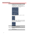
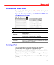
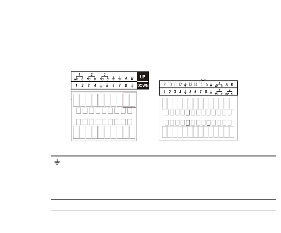
Figure 3-1 Alarm Input and Output of HD-DVR-1004, HD-DVR-1008
(Left) and HD-DVR-1016 (Right)
Parameter Grounding Alarm
Ground line
Alarm Input
HD-DVR-1004: 1, 2, 3, 4 become valid in low voltage; 5, 6, 7, 8
are not effective.
HD-DVR-1008: 1-8 become valid in low voltage.
HD-DVR-1016: 1-16 become valid in low voltage.
Relay Output NO C 1-NO C, 2-NO C, 3-NO C Three Normal Open activation outputs.
RS-485 A/B
RS-485 communication port. They are used to control devices
such as PTZ. Please parallel connect 120Ω between A/B cables if
there are too many PTZ decoders.
Alarm Input Port
4-ch (HD-DVR-1004)/8-ch (HD-DVR-1008)/16-ch (HD-DVR-1016)
grounding alarm inputs. (Normal open or Normal close type)
Please parallel connect COM end and GND end of the alarm detector
(Provide external power to the alarm detector).
Please parallel connect the ground of the DVR and the ground of the alarm
detector.
Please connect the NC port of the alarm sensor to the DVR alarm input
(ALARM)