


M5 (8 mm length) (4 pcs) screws
M4 (10 mm length) (2 pcs) screws T4 (12 mm length) (2 pcs) screws
Note: The appearance of your TV may
dier from the illustrations in this guide.
AV IN
HDMI 2
A
ANT /
C AB LE IN
(ARC)
HDMI 1
(DVI)
HDMI 3
DIGITAL
OUTPUT
US B
(COAXIAL)
VIDEO
AUDIO
L
R
COMPON E NT
IN
P B
P
R
AV IN
Y
AV IN
HDMI 2
ANT /
C AB LE IN
(ARC)
HDMI 1
(DVI)
HDMI 3
DIGITAL
OUTPUT
US B
(COAXIAL)
VIDEO
AUDIO
L
R
COMPON E NT
IN
P B
P
R
AV IN
Y
AV IN
HDMI 2
ANT /
C AB LE IN
(ARC)
HDMI 1
(DVI)
HDMI 3
DIGITAL
OUTPUT
US B
(COAXIAL)
VIDEO
AUDIO
L
R
COMPON E NT
IN
P B
P
R
AV IN
Y
AV IN
HDMI 2
ANT /
C AB LE IN
(ARC)
HDMI 1
(DVI)
HDMI 3
DIGITAL
OUTPUT
US B
(COAXIAL)
VIDEO
AUDIO
L
R
COMPON E NT
IN
P B
P
R
AV IN
Y
M4 screws (2)
T4 screws ((2)
M5 screws (4)
COMPONENT
OUT
AUDIO/VIDEO
OUT
CABLE
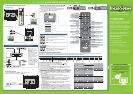
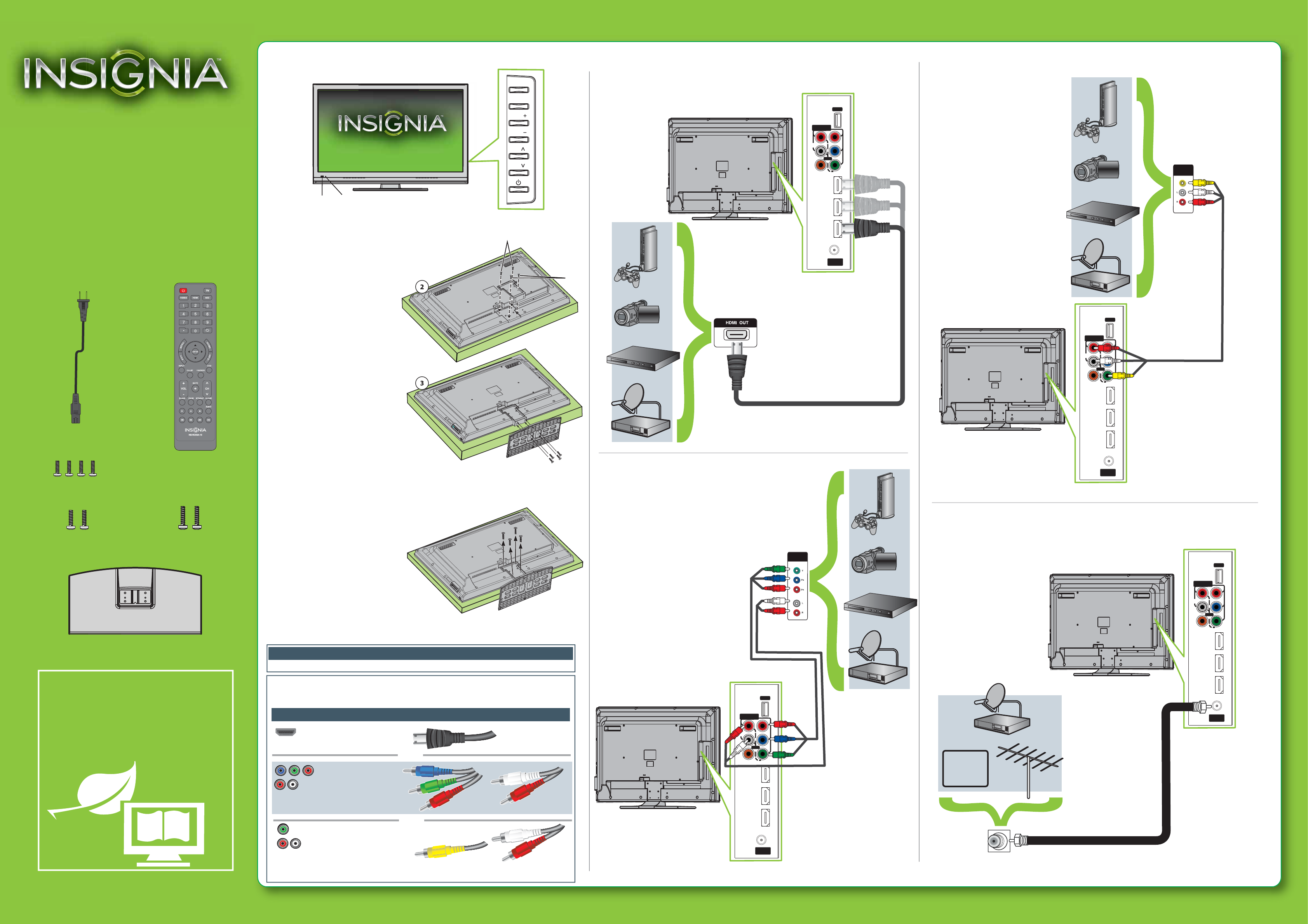
Note: Cable is not provided.
Note: Cables are not provided.
Note: Cable is not provided.
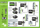
Identifying cables
Your TV has several connection types for connecting devices. For the best video quality,
connect a device to the best available connection.
You can use the HDMI 1(DVI) jack to connect a DVI device to your TV. You need to attach an
HDMI-to-DVI adapter to the end of the HDMI cable that connects to the DVI device’s jack.
Connection type
Video quality
Cable connector
HDMI video/audio
Best
Component video
and analog audio
Better
Good
OR
OR
This apparatus is intended to be supported by a UL Listed wall mount bracket.
Warning
Composite video
and analog audio
Front features
Connecting a DVD or Blu-ray player, cable box,
satellite receiver, camcorder, or game station
Using an HDMI cable (best)
Using component cables (better)
Using composite cables (good)
Connecting an antenna/cable wall jack
Connect a coaxial cable (not included) to the ANT/CABLE IN jack on the side
of your TV and to the antenna/cable wall jack.
39" LCD TV
QUICK SETUP GUIDE
NS-39L240A13
Thank You
for purchasing this ne Insignia television.
We hope you enjoy the quality and reliability
of this product for years to come.
_______________________________
Remote control and 2
AAA batteries
WE ARE GOING GREEN!
A copy of your User Guide is not provided in
the box but is available online.
Go to www.insigniaproducts.com, click
Support & Service, enter your model
number in the Product Search eld,
then click Search.
TV stand
AC power cord
CH
VOL
VOL
MENU
INPUT
CH
Remote
control sensor
Power
indicator
Note: Connect your Yellow video cable
to the Green Y/VIDEO jack.
Installing the stand
1
Carefully place your TV face-down
on a cushioned, clean surface to
protect the screen from damages
and scratches.
2
Secure the stand column to the
back of the TV with the two M4
and two T4 screws provided.
3
Make sure that the wide portion
of the stand faces the front of
your TV, then align the stand with
the stand column and secure the
stand to the TV with the four M5
screws provided.
Installing a wall-mount bracket
1 Carefully place your TV screen face-down on a cushioned, clean
surface to protect the screen from damages and
scratches.
2
Remove the screws that secure the stand
column to the TV screen, then
remove the stand column.
3
Attach the wall-mount bracket to
your TV using the mounting holes
on the back of your TV. See the
instructions that came with the
wall-mount bracket for
information about how to
correctly hang your TV.