WARNING: In explosive atmospheres, electrical power must be removed from the transducer before attempting to
remove the cover and until the cover is fully reinstalled. Failure to do so may result in electrical spark or explosion.
CAUTION: Only attempt electrical adjustments as described below. Any mechanical adjustments made will void the
warranty.
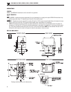
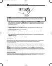
1. Remove the cover to gain access to the "SPAN",(marked S), "FINE ZERO",(marked Z) and the "DAMPING", (3/4 turn low
profile) potentiometers. The unmarked pot “COURSE ZERO”, is used only for major calibration range changes. This
adjustment should only be attempted by factory trained personnel. For NEMA 1 enclosure, just slide open the access
door on the top of the cover.
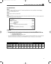
2. Set electrical input signal to 0% (e.g. 4 mA or 0 VDC).
3.
FORWARD ACTING UNITS: Using "FINE ZERO" potentiometer, adjust output pressure to 0% output (e.g. 3 psi).
4. Set electrical input signal to 100% (e.g. 20 mA or 10 VDC).
5. FORWARD ACTING UNITS: Using "SPAN" potentiometer, adjust output pressure to 100% output (e.g. 15 psi).
6. Repeat steps 2 through 5 until output pressures are properly set.
NOTE: Under certain circumstances, output pressure may exhibit cycling action. To eliminate this condition, use the
"DAMPING" potentiometer.
7. Reinstall cover using original screws and gaskets, if equipped.
MAINTENANCE
When used properly, these transducers should provide more than one million cycles without failure. If a situation should
occur in which the transducer's behavior is abnormal, the cause is usually related to a pneumatic problem.
ELECTRICAL MAINTENANCE
An electrical problem must be isolated by a skilled technician. The power source and all wiring should be checked first.
Circuit board failures are very rare, and can be confirmed by the following method. Loosen the screws, or posts that hold
the circuit board in place. Unplug the blue connector from the circuit board, and insert two small pieces of wire into the con-
nector.
IMPORTANT: Connect a current source with the polarity as follows. Positive to the (RED) coil wire and Negative to the
(BROWN) coil wire of 10 mA to the connector, which powers the yellow coil. With supply pressure on, the unit should pro-
duce an output pressure equivalent to 80% or more of the maximum output pressure. If there is little or no output, then the
unit is clogged. Should it produce an adequate output pressure, then the circuit board is the primary suspect. The unit must
be returned to the factory for repair.
PNEUMATIC MAINTENANCE
All 510 and 511 Series transducers also have an internal orifice filter, but if contaminates do invade the transducer, they can
clog the internal orifice and block the flow, or jam open the internal supply valve. The problem can be corrected through
replacement of the orifice (see TABLE 5: KITS) or by cleaning the internal supply valve, or both.
M-4109/1104 IP510, EP510, IP511, EP511 SERIES
A
6
)-T1001.qxd 4/11/05 3:23 PM Page 6


