


1-12 (No.YA476)
3.4 MEMORY IC REPLACEMENT
• This model uses the memory IC.
Memory IC: IC702 on MAIN PWB
The memory IC memorizes data for correctly operating the video and deflection circuits. When replacing the memory IC, be sure to
use the same type IC written with the initial values of data. In other words, use the specific IC listed in "PRINTED WIRING BOARD
PARTS LIST". For its mounting location, refer to "ADJUSTMENT LOCATIONS".
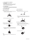
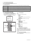
3.4.1 MEMORY IC REPLACEMENT PROCEDURE
1. Power off
Switch off the power and disconnect the power plug from the
AC outlet.
2. Replace the memory IC
Be sure to use the memory IC written with the initial setting
values.
3. Power on
Connect the power plug to the AC outlet and switch on the
power.
4. System constant check and setting
* It must not adjust without signal.
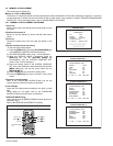
(1) Press the [DISPLAY] key and the [PICTURE MODE] key
of the REMOTE CONTROL UNIT simultaneously.
(2) The SERVICE MODE screen of Fig. 1 will be displayed.
(3) While the SERVICE MODE is displayed, press the
[DISPLAY] key and the [PICTURE MODE] key
simultaneously, and the SYSTEM CONSTANT SET
screen of Fig. 2 will be displayed.
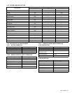
(4) Check the setting values of the SYSTEM CONSTANT
SET. If the value is different, select the setting item with the
[MENU /] key, and set the correct value with the
[MENU /] key.
(5) Press the [OK] key to memorize the setting value.
(6) Press the [DISPLAY] key twice, and return to the normal
screen.
5. Receiving channel setting
Refer to the OPERATING INSTRUCTIONS and set the
receive channels (Channels Preset) as described.
6. User settings
Check the user setting items according to the given in page
later.
Where these do not agree, refer to the OPERATING
INSTRUCTIONS and set the items as described.
7. SERVICE MODE setting
Verify what to set in the SERVICE MODE, and set whatever is
necessary (Fig.1).
Refer to the SERVICE ADJUSTMENT for setting.
Fig.1
Fig.2
EXIT
MENU key
MENU key
MENU key
DISPLAY key
OK key
PICTURE MODE
key
MENU key
KEY ASSIGNMENT OF REMOTE CONTROL UNIT
1. IF
3. AUDIO
5. VSM W/B
7. PLUG & PLAY (ON)
2. V/C
4. DEF
6. S TATUS
SERVICE MENU
1-7 : SELECT DISPLAY : EXIT
SERVICE MENU
******* **** ***** *****
**** **** *** ***
SYSTEM CONSTANT-1
: SEL : OPE
COMB
TILT
: MULTI
:NO
:NO
TEXT
:NO
SUPER BASS
:NO
LANGUAGE
:EV
SYSTEM CONSTANT SET 1
SYSTEM
DISP : EXIT
SYSTEM CONSTANT-2
: SEL : OPE
BLUE BACK MUTE
:PB
:NO
ECO SENSOR
:ECO
COLOUR AUTO
:NO
:NO
BILINGUAL
:NO
SYSTEM CONSTANT SET 2
SOUND
DISP : EXIT
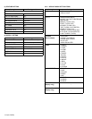
SYSTEM CONSTANT-3
: SEL : OPE
:YES
SYSTEM CONSTANT SET 3
SURROUND
:NOPICTURE BOOSTER
:YESCOMPONENT
:YESPIP
:YES
:YES
S INPUT
MAXX BASS
DISP : EXIT
INTER CARRIER