


(No.YA476)1-29
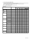
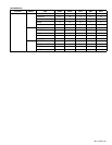
4.9 ADJUSTMENT PROCEDURE
4.9.1 CHECK ITEM
Item
Measuring
instrument
Test point Adjustment part Description
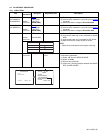
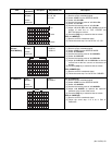
B1 VOLTAGE
[AV-21MXP6/V,
AV-25MXP6/V]
DC voltmeter
Remote
control unit
CN00B connector
1-pin:TP-B1
3-pin:TP-E
[MAIN PWB]
(1) Receive any broadcast.
(2) Connect a DC voltmeter to 1-pin and 5-pin of CN00B
connector.
(3) Make sure that the voltage is DC134.5V ±2.0V.
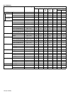
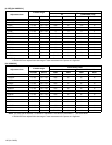
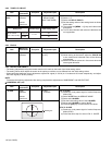
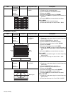
B1 VOLTAGE
[AV-29MXP6/V]
DC voltmeter
Remote
control unit
CN00X connector
1-pin:TP-B1
5-pin:TP-E
[MAIN PWB]
(1) Receive any broadcast.
(2) Connect a DC voltmeter to 1-pin and 5-pin of CN00X
connector.
(3) Make sure that the voltage is DC134.5V ±2.0V.
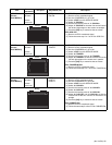
HIGH VOLTAGE HV voltmeter
Remote
control unit
CRT anode
Chassis GND
(1) Receive any broadcast.
(2) Connect the earth clip of HV voltmeter to chassis
GND.
(3) Connect the probe of HV voltmeter to CRT anode.
(4)
Make sure that the voltage is table in the left.
NOTE:
• Remove the probe before removing the earth clip.
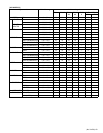
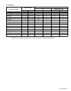
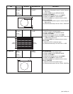
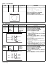
IF VCO Remote
control unit
[1.IF]
1.VCO
• Under normal conditions, no adjustment is required.
• Confirmation adjustment.
(1) Select 1.IF from the SERVICE MODE.
(2) Select <1.VCO>
(3) Receive any broadcast.
(4) Check the ←(Arrow) posspition between the ABOVE
REF. and BELOW REF.
MODEL VOLTAGE
AV-21MXP6/V 28.5kV ( 1.5kV)
AV-25MXP6/V
AV-29MXP6/V
30.5kV ( 1.5kV)
31.5kV (+1kV - 1.5kV)
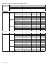
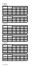
TOO HIGH
ABOVE REFERENCE
JUST REFERENCE
BELOW REFERENCE
TOO LOW
VCO (CW)
. MHz
DISPLAY : EXIT
Receiving frequency
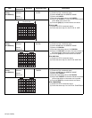
YELLOW
1. VCO
2. DELAY POINT
IF SERVICE MENU
DISPLAY : EXIT1 : SELECT