3
AV-32H35SAE / LCT1364-001A-U / English
Setting up your TV
Caution
• Turn off all the equipment including the TV before connecting anything.
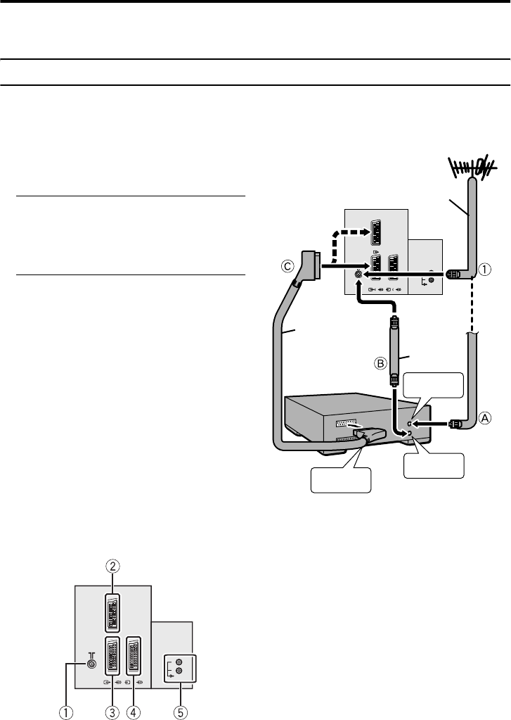
Connecting the aerial and VCR
• The connecting cables are not provided.
• For further details, refer to the manuals provided with the devices to be connected.
If connecting a VCR, follow A
AA
A
→
B
BB
B
→
C
CC
C.
If not connecting a VCR, follow 1
11
1.
To operate T-V LINK functions, a T-V
LINK compatible VCR must be connected to
the EXT-2 terminal on the TV. For details
about T-V LINK functions, see “T-V LINK
FUNCTIONS” on page 6.
• A video can be viewed from the VCR
without performing C. For details, refer
to your VCR instruction manual.
• To connect additional external devices,
please see “Additional preparation” on
page 37.
• To connect speakers and amplifier, please
see “Connecting Speakers/Amplifier” on
page 38.
• When a decoder is connected to a T-V
LINK compatible VCR, set the
DECODER (EXT-2) function to ON. For
details, see “Using the DECODER (EXT-
2) function” on page 36. Otherwise, you
will not be able to view scrambled
channels.
Rear Panel
1 Aerial socket (3)
2 EXT-1 terminal (3, 23, 37)
3 EXT-2 terminal (3, 6, 23, 37)
4 EXT-3 terminal (23, 37)
5 AUDIO OUT terminal (38)
EXT-2
S
EXT-3
S
R
AUDIO OUT
L
EXT-1
75-ohm
Coaxial
Cable
21-pin
SCART
Cable
Back of the TV
75-ohm
Coaxial
Cable
AV IN/OUT
Terminal
To Aerial
Output
To Aerial
Input
VCR
Aerial
EX
T
-
2
S
E
XT-
3
S
R
A
U
D
IO
O
U
T
L
EXT-1
AV-32H35SAE.book Page 3 Wednesday, March 12, 2003 4:29 PM


