


18
V
L
RR
L
/
MONO
Y
C
B
C
R
/
V
V
S
OVER
L
R
/
MONO
OUTPUT
VIDEO-1
INPUT
COMPONENT
(VIDEO-2)
INPUT
V
L
RR
L
/
MONO
Y
C
B
C
R
/
V
V
S
OVER
L
R
/
MONO
OUTPUT
VIDEO-1
INPUT
COMPONENT
(VIDEO-2)
INPUT
BASS
SPEAKER
OUT
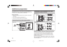
The illustrations shown in this section are for AV-21MT35 and
AV-29VA15 only, which are used for explanation purpose. Your
TV may not look exactly the same as illustrated.
Before connecting
• Read the manuals provided with the devices for the proper
connection.
• Turn off all the devices including the TV.
• Note that connecting cables are not supplied.
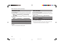
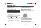
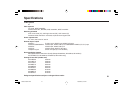
Connecting to front video input terminal
Additional preparation
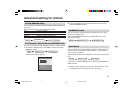
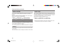
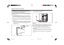
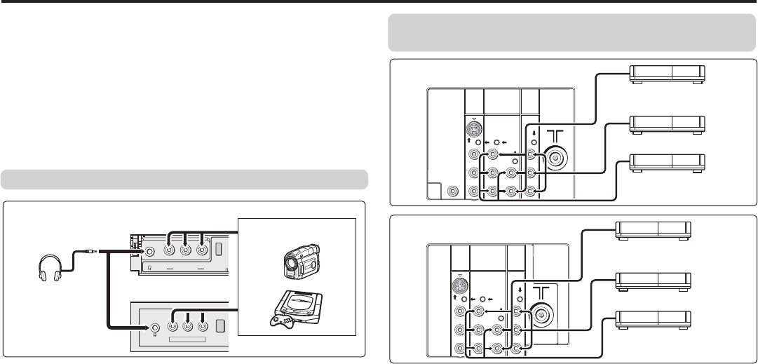
Connecting to rear component/video input
terminal and output terminal
MENU
OK
V
R
L
/
M
O
N
O
IN
(V
ID
E
O
-3
)
MENU
OK
L/MONO
IN (VIDEO-3)
VR
Front of TV
Headphones
AV-21MT35
AV-29VA15
Camcorder or TV game
When you use VIDEO-1 INPUT, you should choose to connect
S-VIDEO or video input. If S-VIDEO connector and video input
are connected at the same time, no picture displays on the
screen and the message “PLEASE DISCONNECT VIDEO-1
CABLE!” appears. In this case, you should disconnect either
S-VIDEO or video input.
When connecting to COMPONENT (VIDEO-2) input, depending
on the connection, choose the appropriate video input using the
menu (see page 16).
Rear of TV
AV-21MT35
VCR (for playing)
DVD player (composite signals)
VCR (for recording)
DVD player
(component video signals)
Rear of TV
AV-29VA15
VCR (for playing)
DVD player (composite signals)
VCR (for recording)
DVD player
(component video signals)
GGT0072-001B-H-EN 29/04/2005, 9:19 AM18