


6 Connections
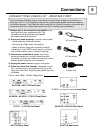
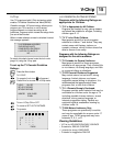
There are two basic types of antenna or cable connections:
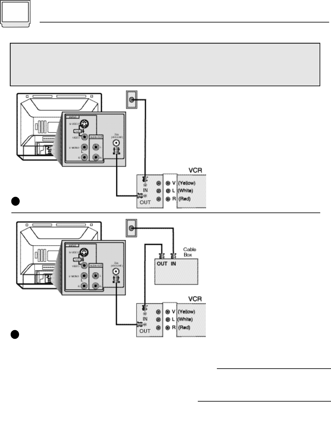
• If you have an antenna or have a cable system that does not require you use a cable box to
select channels, please refer to Diagram #1.
• If you use a cable box to access any or all the channels, please refer to Diagram #2.
1) Connect the antenna or cable
TV wire from the wall outlet, in
to the RF Input on your VCR.
2) Connect an RF cable from the
VCR Output, in to the RF input
on the back of the TV.
• If you want to use the VCR as a
separate tuner (not be required to
have the VCR set to channel 3 or
4 to watch the TV), you can
connect a two-way splitter in
between the Cable and VCR
connections.
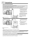
1) Connect the antenna or cable
TV wire from the wall outlet, in
to the RF Input on your Cable
Box.
2) Connect an RF cable from
the Cable Box Output, in to
the VCR’s RF input.
3) Connect an RF cable out from
the VCR’s output in to RF input
at the back of the TV.
Cable and VCR Connections
1
2
Illustration of AV-27120
Illustration of AV-27120
Notes
• Refer to the Cable Box or VCR’s instructions for more information on its operation.
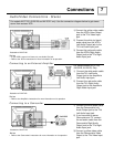
You can connect a pair of headphones or earphone to the television using the headphone jack on the front panel.
1) Plug a headphone/earphone jack into the headphone jack on the television’s front panel.
Headphone Connection (available on 13 and 20 inch models)
You may also choose to connect video devices (VCR, Camcorders, etc) by using an S-Video Cable. S-Video
may be substituted in any of the connections diagrams included here. To use S-Video:
1) Plug an S-Video cable out from the video device and in to the TV’s S-Video Input.
Keep the audio connections the same as shown in the diagrams.
S-Video Connection (available on model AV-27120 only)