


4
CONTENTS
1 INTRODUCTION
1-1 Major features .............................................. 5
1-2 Maintenance ................................................ 5
1-3 Precautions .................................................. 6
1-4 Precautions for use of head cleaning
tape .............................................................. 7
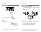
2 CONTROLS, CONNECTORS AND
DISPLAYS
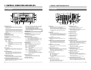
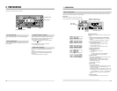
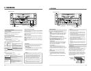
2-1 Front panel................................................... 8
2-2 Rear panel ................................................... 9
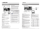
2-3 On-screen display ...................................... 10
2-4 LCD display................................................ 11
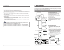
3 CONNECTIONS
3-1 Video system connections ......................... 12
3-2 Audio system connections ......................... 13
3-3 Other connections...................................... 14
3-4 Editing system examples ........................... 15
4 MENU SWITCHES
4-1 Menu switch organization .......................... 19
4-2 Menu switch details ................................... 20
5 PREPARATION
Turn the power ON/OFF ................................... 24
Loading/unloading a cassette ........................... 24
Audio monitor selection..................................... 24
Built-in clock setting .......................................... 25
6 RECORDING
Recording preparation ...................................... 26
Recording.......................................................... 26
Audio dubbing ................................................... 27
Reference ......................................................... 27
This unit is designed for professional use.
This video cassette recorder uses the MiniDV format.
Use only video cassettes bearing the MiniDV mark.
Please note that it may be unlawful to use any material
recorded from TV broadcast programs or pre-recorded
programs without the consent of the owner of
copyright, except in cases where this material is
recorded exclusively for personal use.
JVC is not liable for compensation for loss or damage
to recordings in the event this unit fails to record or play
back correctly due to a malfunction of the unit itself or
as a result of the use of a defective video cassette.
This unit is designed for use as a recorder/player.
Insert editing is not possible.
7 PLAYBACK
Playback preparation ........................................ 28
Playback ........................................................... 29
Repeat play....................................................... 29
8 EXTERNAL TIMER-START FUNCTION
Playback ........................................................... 30
Recording.......................................................... 30
9 TIME CODE
Display .............................................................. 31
Preset................................................................ 31
Recording.......................................................... 33
Playback ........................................................... 34
Reference ......................................................... 34
10SUPER SCENE FINDER FUNCTION........ 35
11BACKUP RECORDING FUNCTION..........36
12RS-232C INTERFACE
12-1 Command tables..................................... 37
12-2 RS-232C specifications .......................... 38
12-3 RS-232C commands .............................. 39
13TROUBLESHOOTING
13-1 Warning indicators ................................... 46
13-2 Other problems........................................ 48
14APPENDIX
1
14-1 Optional equipment................................. 48
15SPECIFICATIONS ..................................... 49
Compatible models of the RM-G800 have an X on the
packing case and on the serial number plate (next to
the model name) on the base.
If your RM-G800 is not marked with an X, you will need
to upgrade the software in order to use it with the BR-
DV600UA.
A software upgrade is available at a nominal fee. For
more information, contact your JVC dealer.
5
1 INTRODUCTION
1-1 Major features
5
MiniDV format
High-quality picture and sound thanks to digital
technology
5
DV in/out (IEEE 1394) connector enabling signals to be
transferred to or from any device equipped with IEEE
1394 input/output
5
Composite, Y/C and component inputs/outputs
5
Sync lock function for audio and video signals
There is no lip link shift even during extended recording
5
JVC bus and RS-422 serial remote interfaces
5
RS-232C interface (optionally available)
5
2-way power supply system (AC 120 V, DC 12 V)
(U MODEL)
2-way power supply system (AC 220 V – 240 V,
DC 12 V) (E MODEL)
5
Audio dubbing function (32 kHz sampling rate)
5
Compact, lightweight design
5
SMPTE time code recording and playback (U MODEL)
EBU time code recording and playback (E MODEL)
5
External timer-start function
5
External sync signal input connectors
5
Time code IN/OUT connectors provided
1-2 Maintenance
Maintenance consultation
Consult your local JVC dealer for more information about
maintenance scheduling and costs.
Head cleaning
Recording and playback with clogged heads may result in
block noise or sound interruption.
In this case, clean the heads.
Use an exclusive head cleaning tape M-DV12CL to clean
the tape running system. For cleaning procedures and
handling precautions, refer to page 7.
After cleaning the heads, check that recording and
playback function properly before using the unit for any
important operations.
Cleaning
Use a soft cloth to clean the cabinet. Do not use benzene
or thinner as these may melt or cloud the cabinet surface.
To remove excessive dirt, clean the unit with a mild
detergent diluted with water, then wipe it with a dry cloth.
The video cassette recorder/player incorporates precision
components. Continued use of the VCR without
maintenance may lead to malfunctions. Regular
maintenance is necessary to prevent malfunctions and
maintain the performance level required for professional
use.
• Maintenance: Just as regular oil changes, brake checks,
and tune-ups are essential to keep your car running well
over a long period, your VCR must be maintained
regularly to ensure optimum long-term performance.
The information below will help you determine a
maintenance schedule that will ensure optimum
performance over a long period of time.
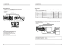
Hour meter indication
The hour meter can be displayed by selecting
“HM: HOUR
METER” on the menu switch setting screen. For details,
refer to “Menu Switches” on page 19.
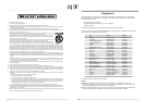
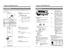
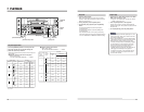
Details for maintenance
Depending on the operation time, clean, inspect or replace
the following mechanism components.
Operating time 500H 1000H 1500H 2000H
Drum assembly
(including the heads)
⅙⅙⅙●
Head cleaner ଁ●ଁ●
Tape guide roller ⅙ଁଁ●
Rotary encoder מଁמ●
Belt and gear ଁ●ଁ●
Driving system parts ⅙⅙ଁ●
This table should be used for reference only.
Actual maintenance requirements will vary according to
how the unit is used.
מ
: Inspection
⅙
: Cleaning inspection, adjustment
ଁ
: Cleaning inspection, replacement if required
●
: Replacement