


10
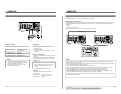
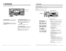
2-3 On-screen display
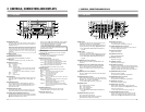
2 CONTROLS, CONNECTORS AND DISPLAYS
Five types of indication are available.
2. Menu switch
This indication is used to set the menu switch.
Shown when the [MENU] button is pressed.
Press it once again to restore the previous display.
੬
See “MENU SWITCHES
” on page 19.
3. Hour meter
Shows the rotating head usage time.
Select “HM: HOUR METER”
on the menu switch’s group
select screen.
4. Tape remaining time
Shows the tape remaining time.
Shown when the No. 505 <REMAIN ENABLE> menu
switch is set to “ON”.
5. Warning message
Automatically shown when an abnormality occurs.
੬
See “Warning indicators”
on page 46.
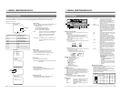
The on-screen display can be viewed on a monitor connected to the rear panel
’
s [VIDEO MONITOR OUT] connector when the
No. 500 <ON SCREEN> menu switch is set to
“ON”. Pressing the [MENU] button will bring up the menu switch display
regardless of this setting.
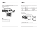
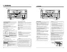
Mode
Time display
Counter mode
Tape counter
Counter mode indication Time display contents
CTL CTL counter data
TCR Time code reader data
TCG Time code generator data
UBR User bits reader data
UBG User bits generator data
TIME Time
DATE Date
ETCG External time code generator
data
EUBG External user bits generator data
1. Tape counter
The type of data shown on the tape counter display is set
with the [COUNTER] switch and menu switch.
Related settings
[COUNTER] switch (front panel)
No. 504 <INFORMATION SELECT>
No. 514 <TIME DISPLAY SELECT>
Mode: Shown when the No. 504 <INFORMATION
SELECT> menu switch is set to
“MODE +
TIME”. In this case, the unit’s operation
status can be checked on the monitor
screen.
Time display: The indications shown in the table on the
left are available with the counter mode
indication.
Menu switch
Hour meter
Tape remaining time
Warning code
(In case of condensation)
STOP
TCR 12:00:00:00
00~~ : SYSTEM
00~~ :TIMECODE
00~~ : ONSCREEN
M : HOUR METER
3
4
5
H
00~~ :AUDIO2
00~~ : SERVO/ SYSTEM0
00~~ :VIDEO1
( HOUR METER )
H : DRUM HOUR METER
00000
D
0H
TCR 00 :12: 00:00
01:00
WARNING 0201
CONDENSATI ON ON DRUM
Minute
Hour
11
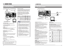
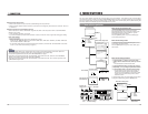
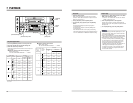
2-4 LCD display
2 CONTROLS, CONNECTORS AND DISPLAYS
1
Counter display section
Three types of indications can be displayed in the counter
display section.
(1) Tape counter
Normally, the indication selected with the [COUNTER]
switch is shown. When the No. 516 <DISPLAY
SELECT> menu switch is set to
“CLOCK”, the time and
date are shown.
੬
See “Built-in clock setting
” on page 25.
(2) Menu switch
In the menu switch setting mode, menu switch items are
shown one at a time.
(3) Warning code
When this unit malfunctions, the nature of the problem is
indicated by an error code.
੬
See “Warning indicators” on page 46.
• In the Operate Off mode, “oPE-oFF” is shown.
2
Tape running indication
Shows the tape running conditions.
Audio dubbing mode
Recording mode
Rewind mode
Stop mode
Fast-forward mode
Play mode
Pause mode
Reverse search mode
Fast-forward search mode
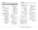
3
Battery indicator
When this unit is powered by a battery and the battery
voltage level drops below the specified value, this indicator
blinks (“off” in normal operation), to show that battery
voltage is insufficient. This indicator will also blink when the
Operate Off mode is engaged (since voltage output from
the battery drops in this mode).
4
Cassette mark
This mark lights to show that a cassette is loaded.
This mark is shown even in the Operate Off mode.
5
Indicators
AUTO OFF: Lights when a problem occurs in this unit.
DEW: Lights when a condensation occurs.
RF: Lights when the heads are clogged and
the signal level drops.
SERVO: Lights when the unit
’
s servo system has
stabilized.
Setting
Menu switch No.
MENU
OVER
OVER
HMSF
AUD LOCK
32k 44.1k 48k
SLAVE PB NDF
SERVO RF
DEW
AUTO OFF
HOLD
CH 2/4
CH 1/3
dB40 30 20 10
0
1
2
34
5
6
SP
LP
AUD LOCK: Lights when the video and audio
sampling clocks (at 48 kHz) are
synchronized in the Play mode. Lights in
the Recording mode and EE mode.
Does not light when the sampling rate is
32 kHz or 44.1 kHz.
MENU: Lights in the menu switch setting mode.
32K/44.1K/48K: Shows the frequency of the digital audio
signal sampling rate. In the Record and
EE modes, the frequency set with No.
245 <SAMPLING RATE> menu switch is
shown. In the Play mode, the playback
audio signal mode is shown. The 44.1K
indication is shown only in the Play
mode.
PB: Lights when playback signals are output.
NDF: Lights when the non-drop mode is set for
time code. (U MODEL)
DF: Lights when the drop mode is set for
time code. When the CLOCK mode is
engaged for the LCD display in the REC
or EE mode, “DF” lights even though the
NDF mode is set for time code. (U MODEL)
HOLD: Lights in the time code or user bits
setting mode and in the date and time
setting mode.
SP/LP: Shows the recording or playback speed.
Please note that LP mode recording and
playback is not possible with this unit. If
you try to play back a tape recorded in
the LP mode, the
“LP inh” indication is
shown and the VCR enters the Stop
mode.
SLAVE: Lights when time code signals are input
to the 6 [TIME CODE IN] connector on
the rear panel to synchronize with video
input signals. Blinks when they are not
in sync with video input signals.
*Even though the [SLAVE] indicator
lights, time code data from an external
time code generator connected to the
[TIME CODE IN/OUT] connectors may
not be effective.
• During play
The playback time code data is output
to the 8 [TIME CODE OUT]
connector.
• When the No. 460 <TC DUPLICATE>
menu switch is set to
“ON”, time code
data input to the [DV IN] connector is
recorded.
6
Audio channel indication
Shows the audio channel of the signal output from the rear
panel’s [AUDIO OUT] connectors.
Indication and output signals can be switched with the
front panel’s [AUDIO OUTPUT] switch only when 32 kHz
sampling rate signals are played back.
In other modes, the indication and output signals are fixed
as shown in the table below.
Sampling rate 32K 48K 44.1K
Mode
PB/ A.DUB
EE/REC PB EE/REC PB
A.DUB PAUSE
⅜מ
⅜⅜⅜⅜
⅜
⅜
ממממ
⅜מממממ
Fixed Fixed Fixed Fixed
Fixed
CH 2/4
CH 1/3
CH 2/4
CH 1/3
CH 2/4
CH 1/3
PB: Play mode EE: EE mode
A.DUB: Audio Dubbing mode REC: Record mode