


18
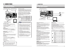
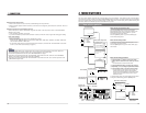
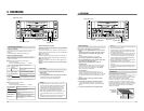
3 CONNECTIONS
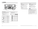
5
Control via the DV connector
• When the DV connector is used for control, assemble editing cannot be performed.
• When the VCR is stopped via the DV connector, a command error message may be returned to the controller. This is not
a malfunction.
5
Cable connection to the [DV IN/OUT] connector
Set the video input to
“DV IN” or “IEEE 1394” using either the switch on the front panel or the No. 108 <VIDEO INPUT
SELECT> menu switch.
੬ See “Recording preparation
” on page 26.
* If you switch the video input when the DV connection is active, turn this unit off and on again after changing the setting.
Menu switch settings
• When controlled by another device via the [DV INPUT] connector
Set the No. 050 <REMOTE SELECT> menu switch to
“IEEE 1394”, “IEEE 1394 + RS422A
”, “JVC BUS + IEEE 1394
”
and “JVC BUS + RS422A + IEEE 1394
”.
• To record the master tape
’
s time code with the DV-to-DV connection, set the No. 460 <TC DUPLICATE> menu switch
to “ON”. (
੬
See “Time code recording
”
on page 33.)
Notes:
• Connect the cable after the menu switches have been set and the connected equipment is turned ON. (When the
BR-DV600UA/EAs are connected to each other, it is not necessary to turn the power ON.)
• To record the playback VCR’s user bits, use the BR-DV600UA/EA as a player.
• When this unit is used with the No. 460 <TC DUPLICATE> menu switch set to “ON”, set the No. 416 <NON DROP/
DROP> menu switch for the tape in the player VCR. (U MODEL)
• When this unit is used with the No. 460 <TC DUPLICATE> menu switch set to “ON”, do not connect any device to the
[TIME CODE OUT] connector.
19
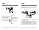
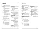
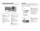
4 MENU SWITCHES
You can set menu switches using either the on-screen display or the counter display. To set switches on the on-screen display,
you will need to connect a monitor to the VCR’s [VIDEO MONITOR OUT] connector. This section explains how to set switches
using the on-screen display. The same procedures apply to switch setting on the counter display, the only difference being that
each menu switch item is indicated by numeric code rather than by name.
Menu switch group
select screen
03:SYNC SELECT
50:REMOTE SELECT
0
0
OFF
02 :OPERAT ION LOCK0
STOP
TCR 12:00:00:00
00~ : SYSTEM
00~ :TIMECODE
00~ : ONSCREEN
M:HOURMETER
3
4
5
H
00~ :AUDIO2
00~ : SERVO/ SYSTEM0
00~ :VIDEO1
[SELECT]
[MENU]
[SET]
[MENU]
[SHIFT]
UA
US+RS42
TO
2AJVC B
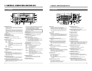
4-1 Menu switch organization
Menu switch group select screen
Pressing the [MENU] button with the normal screen
displayed brings up the menu switch group select screen.
Select the desired group with the [SHIFT +/
–] button.
The selected group number blinks.
Press the [SELECT] button to go to the selected group
menu switch setting screen.
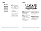
Menu switch setting screen
To access this screen, press the [SELECT] button on the
menu switch group select screen.
Press the [MENU] button to go to the menu switch group
select screen.
Menu switch group select screen
Menu switch setting screen
On-screen display
LINE
08:VIDEO INPUT SELECT1
Y/C
09:VIDEO INPUT21
ON
25:SET UP1
03:SYNC SELECT
UA
50:REMOTE SELECT
US+RS42
0
0
OFF
02 :OPERATION LOCK0
TO
2AJVC B
52 :STEP SLOEW MODE
ARF
53:STOP FUNC.AT SE
ST
0
0
M
CRAH
E
OP
STOP
TCR 12:00:00:00
(HOURMETER)
H :DRUM HOUR METER
00000
D
0H
00 : SYSTEM
00 : TIME CODE
00 : ONSCREEN
M : HOUR ME TER
3
4
5
H
00 : AUDIO2
00 : SERVO/SYSTEM0
00 : VIDEO1
[SET]
[MENU]
[SHIFT]
[SELECT]
[MENU]
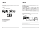
Menu switch setting screen
On-screen display
Switching the
setting screen
[SHIFT] +/–: Item select
SELECT: Changes the setting.
SET: Enters the setting.
Menu switch display
SHIFT
SET
SELECT
SHIFT
MENU
HOLD SHIFT A. DUB
ADVANCE PRESET
MENU
OVER
OVER
HMSF
AUD LOCK
32k 48k
PB NDF
SERVO RF
DEW
AUTO OFF
HOLD
CH 2/4
CH 1/3
dB40 30 20 10
0
V.IN/A.MONI A.OUT COUNTER
DV CTL
TC
UB
CH-1/2
CH-3/4
Y/C
(CPN)
LINE
L
R
MIX
MIX
DATA SET
ABORT
Counter display
When entered
When data has not
been entered yet
Menu switch setting procedure
1
Press the [SHIFT
–/+] button on the menu switch
setting screen to select the menu switch you want to
set.
[The selected menu switch number blinks.
2
Press the [SELECT] button to change the set value.
3
Repeat steps
1
and 2
to change any other menu switches.
4
Press the [SET] button to end menu switch setting.
[The set value is entered and the normal screen is
restored. When entering the data, the indications
shown on the left are displayed. If data has not been
entered and menu switch setting is ended,
“Abort”
indication is shown.
To access another group menu switch setting screen without
ending menu switch setting, press the [MENU] button.