24 EN
AV COMPU LINK Playback
Your VCR is compatible with JVC’s AV COMPU LINK components,
including amplifiers (or receivers) and televisions. AV COMPU
LINK provides one touch control of the audio and video compo-
nents that are linked via their AV COMPU LINK connectors.
For example: simply load a cassette in the VCR and press PLAY
and the AV COMPU LINK components automatically power on,
the TV's AV mode is selected and the VCR goes into play mode.
(PLAY need not be pressed if the cassette's record safety tab is
removed.)
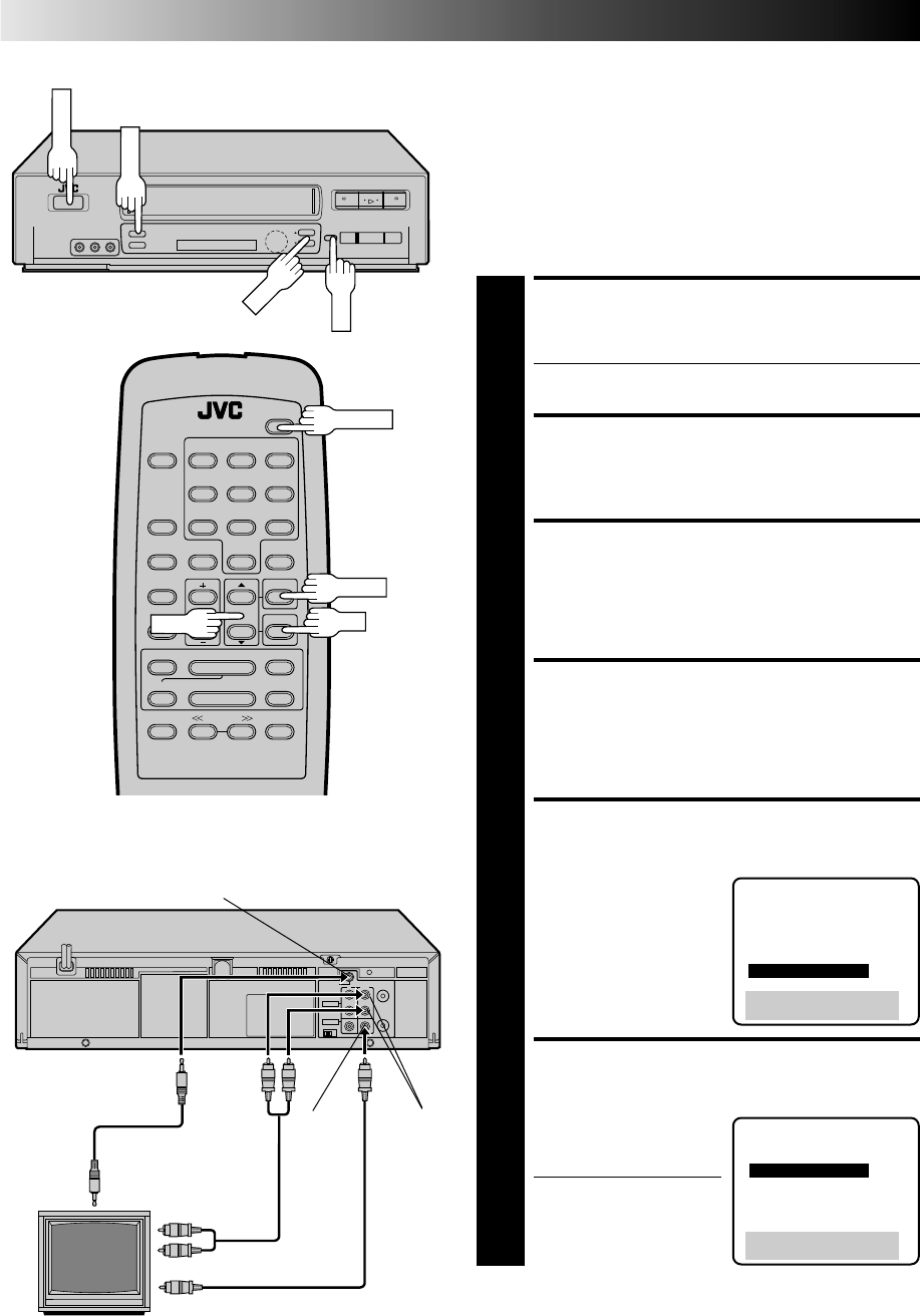
MAKE CONNECTION
1
Connect your VCR to an AV COMPU LINK component
as shown in the illustration at bottom left.
● The mini-plug cable is a mono 3.5 mm mini-plug to
mono 3.5 mm mini-plug connector.
TURN ON THE VCR
2
Press POWER.
ACCESS MAIN MENU
SCREEN
3
Press MENU.
ACCESS FUNCTION SET
SCREEN
4
Press CH
5
∞
to move the highlight bar (arrow) to
“FUNCTION SET”, then press OK.
ACCESS SPECIAL
FUNCTION SCREEN
5
Press CH
5
∞
to move the
highlight bar (arrow) to
“SPECIAL FUNCTION”,
then press OK.
ENABLE AV COMPU LINK
PLAYBACK
6
Press CH5
∞
to move the
highlight bar (arrow) to
“AV COMPU LINK”.
● Make sure the VCR is in
the stop mode before
you change the setting.
2
2
q
5
/
8
6
PLAYBACK AND RECORDING FEATURES (cont.)
3
¶7
8
1¡
1
2
3
4
5
6
7
8
0
9
POWER
MENU
OK
CH
Your VCR
AV COMPU LINK
Television
AUDIO IN
VIDEO IN
VIDEO
OUT
AUDIO
OUT
PAUSE/
AV COMPU LINK
AV COMPU
LINK II
(VCR ONLY)
Audio/
Video
cable
(not
supplied)
Example
Mini-plug cable
(not supplied)
FUNCTION
AUTO TIMER
SUPERIMPOSE
2ND AUDIO
AUDIO MONITOR
AUX INPUT
=SPECIAL FUNCTION
PRESS (5,∞), THEN (OK)
PRESS (MENU) TO END
SPECIAL FUNCTION
PAUSE
=AV COMPU-LINK
PRESS (5,∞) TO SELECT
PRESS (MENU) TO END


