


42
HV-32/28P40BU / LCT1684-001A-U / English
Additional preparation
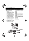
Connecting external equipment
Connect the equipment to the TV, making the
correct rear panel and front panel connections.
Before connecting anything:
• Read the manuals that came with the
equipment.
Depending on the equipment, the
connection method may be different from
the diagram. Also, the equipment settings
may need to change depending on the
connection method.
• Turn off all the equipment including the TV.
• The “Specifications” on page 49 give the
details of the EXT terminals. If you are
connecting equipment not listed in the
following connection diagram, see the
table to choose the best EXT terminal.
• Connecting cables are not supplied.
• When a DVD player is connected to the
EXT-4 component terminal, the TV input
can be automatically changed to EXT-4
by just turning the power supply of the
connected device on. For details, see
“COMPONENT AUTO SELECT” in the
SET UP menu on page 38.
• If the VCR’s audio output is mono, connect
the VCR’s AUDIO OUT (audio output)
terminal and the TV’s EXT-5 audio L/
MONO terminal with an audio cable.
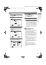
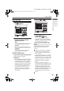
1 VCR (composite signal)
2 VCR (composite signal/S-VIDEO signal)
3 T-V LINK compatible VCR (composite
signal/S-VIDEO signal)
4 Decoder
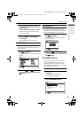
5 DVD player (composite signal/S-VIDEO
signal)
6 DVD player (composite signal/RGB
signal)
7 DVD player (component video signals;
Y/Pb/Pr)
8 TV game (composite signal/RGB signal)
9 TV game (composite signal/S-VIDEO
signal)
0 Headphones
- Camcorder (composite signal/S-VIDEO
signal)
= SCART cable
~ Audio cable
! Video cable
@ S-VIDEO cable
# Component cable
EXT-1
EXT-
4
EXT-2
S
EXT-3
S
AUDIO OUT
L
Pr
Pb
R
L
Y
R
R
L
/
MONO
S
P
EXT-5
R
L
/
MONO
S
P
EXT-5
Back of the TV
Side of the TV
HV-32&28P40BU_Eng.book Page 42 Wednesday, July 21, 2004 5:24 PM