6 C O N N E C T I O N S
#1
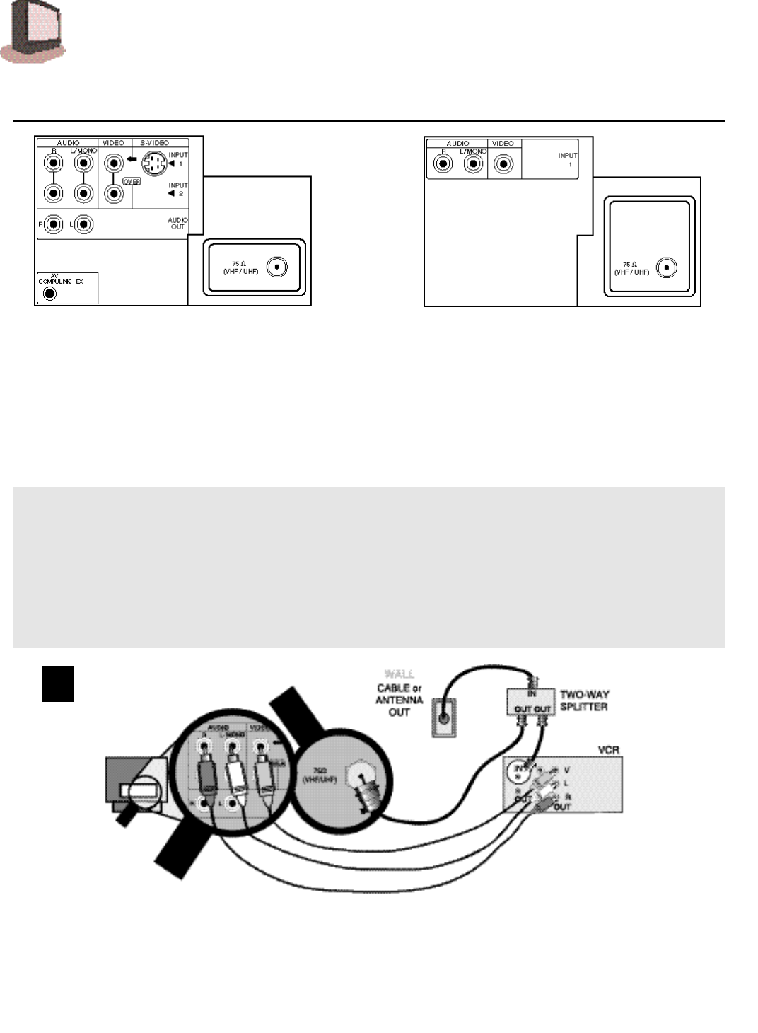
CABLE & VCR CONNECTIONS
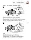
T h e r e are three basic types of antenna or cable hookups. For VCR hookup only, see the Quick Setup Guide.
1 ) If you have an antenna, or a cable TV system that does not re q u i re you to use a cable box to tune the
channels, use D i ag r a m # 1 .
2) If you have a cable system that re q u i res you to use a cable box to access a l l channels, use D i agram #2.
3 ) If you have a cable system that re q u i res you to use a cable box to access c e rt a i n p re m i u m
channels, but not regular basic channels, use D i agram # 3 .
For information on working Picture in Picture (PIP), please see the PIP section on page 28
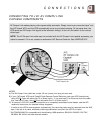
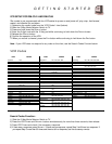
1) Connect cable or antenna RF wire out from the wall, in to the splitter RF input.
2) Connect RF wire Out from the splitter RF output, in to the VCR RF input.
3) Connect RF wire Out from the splitter RF output, in to the TV VHF/UHF input.
4) Connect yellow video cable out from the VCR Video output, in to the TV Video input jack.
5) Connect white audio cable out from the VCR Left Audio output, in to the TV Left Audio input jack.
6) Connect red audio cable o u t f r om the VCR Right Audio output, i n to the TV Right Audio input jack.
❒ If your VCR is mono it has only one audio out jack, connect it to TV L/Mono input.
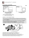
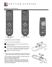
REAR PANEL DIAGRAMS
REAR PANEL DIAGRAM
AV-36050 • AV-32050 • AV-27050
AV-36020 • AV-32020
(The rear panels for the above modes are nearly
identical. The only difference between them is a small
difference in the size of RF panels.)
REAR PANEL DIAGRAM
AV-32015


