


31
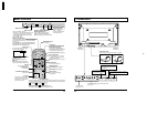
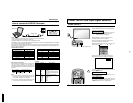
SET UP for Input Signals
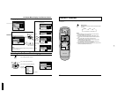
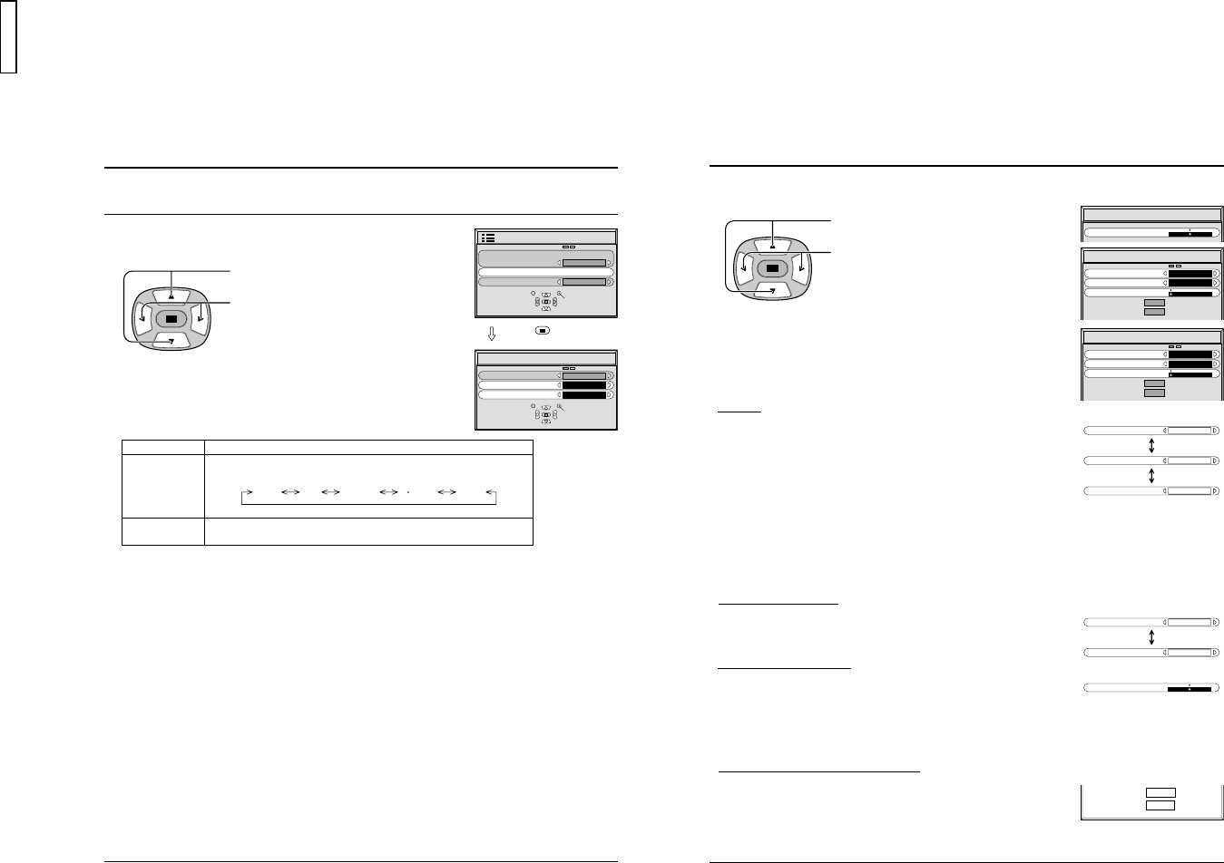
COLOR SYSTEM / AUTO
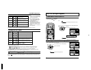
Select SIGNAL from the “SET UP” menu during VIDEO (S-VIDEO) input
signal mode. (“SIGNAL [VIDEO]” menu is displayed.)
Press to select the “COLOR SYSTEM” or
“AUTO”.
SELECT
SET UP
SIGNAL
COMPONENT/RGB-IN SELECT
RGB
OSD LANGUAGE
ENGLISH
(
US
)
RETURN
Mode
Color system
AUTO (4:3)
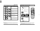
Press to select each functions.
Function
Set the color system to match the input signal. If set to “AUTO”, the color system
is determined automatically.
Set to “NORMAL” to view 4:3 images in an unchanged format when AUTO is
selected. If you would like to view 4:3 images in “Just” format, set to “JUST”.
AUTO PAL SECAM M NTSC NTSC
CHANGE
SELECT
3D Y/C FILTER
(
NTSC
)
COLOR SYSTEM
AUTO
(
4:3
)
ON
AUTO
NORMAL
SIGNAL
[
VIDEO
]
RETURN
Press
(store) button
If the picture image becomes unstable:
With the system set on Auto, under conditions of
low level or noisy input signals the image may in
rare cases become unstable. Should this occur,
set the system to match the format of the input
signal.
32
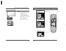
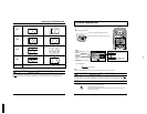
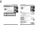
Select SIGNAL from the “SET UP” menu during RGB or PC input signal mode.
Press to select each item.
Press to adjust.
SIGNAL
[
RGB
]
SYNC
PULL-IN RANGE
H
-
FREQ. kHz
V
-
FREQ. Hz
H & V
NARROW
31.5
60.0
CLAMP POSITION
SIGNAL
[
PC
]
SYNC
PULL-IN RANGE
H
-
FREQ. kHz
V
-
FREQ. Hz
H & V
NARROW
31.5
60.0
CLAMP POSITION
The following operation methods are the same for both the SIGNAL [RGB]
and SIGNAL [PC].
SYNC
SYNC
H & V
SYNC
ON VIDEO
SYNC
ON G
Setting RGB sync signal setting:
Confirm that the input is set to RGB INPUT (this setting is valid only for RGB INPUT).
H&V:
The H and V sync signals are input from the HD/VD (BNC) connector.
ON G: Uses a synchronized signal on the Video G signal, which is input
from the G (BNC) connector.
ON VIDEO: Compatible with the scart plug (Europe)
The composite video signal input from the VIDEO input terminal is
used by dividing the sync signals.
Sets the width for different frequencies.
(This setting is the same for both SIGNAL [RGB] and SIGNAL [PC].)
Setting PC sync signal setting:
Confirm that the input is set to PC INPUT (this setting is valid only for PC INPUT).
H&V: The H and V sync signals are input from the HD/VD (BNC) connector.
ON G: Uses a synchronized signal on the Video G signal, which is input from the G (BNC) connector.
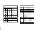
PULL IN RANGE
PULL IN RANGE
WIDE
PULL IN RANGE
NARROW
Displays the H (Horizontal) /V (Vertical) frequencies.
This display is valid only for RGB input and PC input.
Display range:
Horizontal 15.5 - 110 kHz
Vertical 48 - 120 Hz
H-FREQ (kHz) /V-FREQ (Hz)
H
-
FREQ. kHz
V
-
FREQ. Hz
31.5
60.0
SET UP for Input Signals
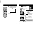
CLAMP POSITION
SIGNAL
[
COMPONENT
]
CLAMP POSITION
Adjusts the clamp position.
The following operation methods are the same for “SIGNAL” menu during
COMPONENT, RGB and PC input signal mode.
Normally, these adjustments are set to appropriate levels and, therefore, do not
need to be altered.
CLAMP POSITION
19
GD-V500PZU