


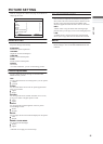

DC IN
(12V)
PC IN
D-SUB
15 PIN
75
(VHF/UHF)
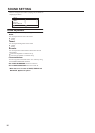
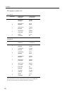
DC IN
(19V)
PC IN
D-SUB
15 PIN
INPUT 2
S-VIDEO
VIDEO
AUDIO
OVER
L
R
Y
Pb
Pr
AUDIO
L
R
COMPONENT
VIDEO
INPUT 1
PC
AUDIO
IN
AUDIO
OUT
R L
SUBWOOFER
OUT
INPUT 2
S-VIDEO
VIDEO
AUDIO
OVER
L
R
Y
Pb
Pr
AUDIO
L
R
COMPONENT
VIDEO
INPUT 1
LT-26C31BUE/SUE/BJE/SJE / LCT1484-001A-U / English (EK)
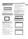
Additional preparation
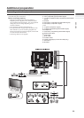
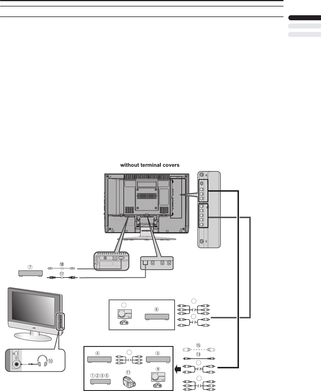
Connecting external equipment
Connect the equipment to the TV, making the correct rear
panel and front panel connections.
Before connecting anything:
• Read the manuals that came with the equipment.
Depending on the equipment, the connection method
may be different from the diagram. Also, the equipment
settings may need to change depending on the
connection method.
• Turn off all the equipment including the TV.
• The “Specifications” on page 29 give the details of the
EXT terminals. If you are connecting equipment not
listed in the following connection diagram, see the table
to choose the best EXT terminal.
• Connecting cables are not supplied.
1 VCR (composite signal)
2 VCR (composite signal/S-VIDEO signal)
3 T-V LINK compatible VCR (composite signal/S-VIDEO
signal)
4 Decoder
5 DVD player (composite signal/S-VIDEO signal)
6 DVD player (component
signal)
7
8 TV game
9 TV game (composite signal/S-VIDEO signal)
10 Headphones
11 Camcorder (composite signal/S-VIDEO signal)
12
Y/Pb/Pr cable(apply for 525i and 525p only)
13
Audio in
14
Video cable
15 S-VIDEO cable
16
D-SUB in
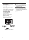
LT-26C31BUE(EK)_Eng.book Page 33 Tuesday, August 5, 2003 2:18 PM
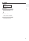
L
PC AUDIO IN
SUBWOOFER
R
PC
PC
14
16
12
DC IN
(12V)
PC IN
D-SUB
15 PIN
75
(VHF/UHF)
(component
signal)
17
Video+Audio cable
Audio cable
18
14
8
12
ENGLISH
23