


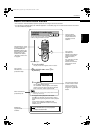
Preliminary knowledge
11
Preliminary
knowledge
English
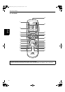
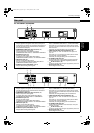
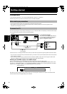
For XV-S402SL/XV-S403SG
For XV-S332SL
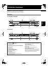
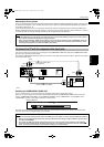
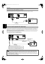
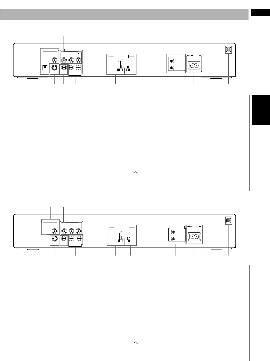
Rear panel
1 DIGITAL OUT jack (OPTICAL/COAXIAL) (18)
Outputs digital audio signals. Both coaxical and optical
connectors are provided. You must select the signal type
correctly according to the external device connected to
via the Preference display.
2 COMPONENT VIDEO OUT jacks (Y/P
B
/P
R
) (17)
Output component video signals.
To enable these jacks, select VIDEO OUT SELECT
(COMPONENT/S-VIDEO) switch to “COMPONENT AND VIDEO”.
3 S-VIDEO OUT jack (16)
Outputs a S-video signal.
To enable this jack, select VIDEO OUT SELECT
(COMPONENT/S-VIDEO) switch to “S-VIDEO AND VIDEO”.
4 VIDEO OUT jack (16)
Outputs a composite video signal.
This jack is enabled regardless of VIDEO OUT SELECT
(COMPONENT/S-VIDEO) switch position.
5 AUDIO OUT jacks (LEFT/RIGHT) (16, 17)
Outputs stereo analog audio signals.
6
VIDEO OUT SELECT switch (COMPONENT/S-VIDEO) (16)
Select “COMPONENT AND VIDEO” or “S-VIDEO AND VIDEO”.
Note that you must change the switch position while
the unit is stopped or while the unit power is off with the
DVD removed.
Otherwise, the changed setting will not be effective.
7 VIDEO OUT SELECT switch (NTSC/PAL) (
16
)
Select “NTSC” or “PAL” to match the color system of
your TV.
Note that you must change the switch position while
the unit power is off (on standby).
Otherwise, the changed setting will not be effective.
8 AV COMPU LINK jacks (52)
Connects with other JVC equipment supporting the AV
Compulink function to facilitate integrated operations.
9 AC IN connector (19)
Connects to the wall outlet using the suppplied AC power cord.
0 Region Code label (15)
Shows Region Code number.
1 DIGITAL OUT jack (COAXIAL) (18)
Outputs digital audio signals. You must select the type
correctly according to the external device connected to
via the Preference display.
2 COMPONENT VIDEO OUT jacks (Y/P
B
/P
R
) (17)
Output component video signals.
To enable these jacks, select VIDEO OUT SELECT
(COMPONENT/S-VIDEO) switch to “COMPONENT”.
3 S-VIDEO OUT jack (16)
Outputs a S-video signal.
To enable this jack, select VIDEO OUT SELECT
(COMPONENT/S-VIDEO) switch to “S-VIDEO
AND VIDEO
”.
4 VIDEO OUT jack (16)
Outputs a composite video signal.
To enable this jack, select VIDEO OUT SELECT
(COMPONENT/S-VIDEO) switch to “S-VIDEO AND VIDEO”.
5 AUDIO OUT jacks (LEFT/RIGHT) (16, 17)
Outputs stereo analog audio signals.
6
VIDEO OUT SELECT switch (COMPONENT/S-VIDEO) (16)
Select “COMPONENT” or “S-VIDEO AND VIDEO”.
Note that you must change the switch position while
the unit is stopped or while the unit power is off with the
DVD removed.
Otherwise, the changed setting will not be effective.
7 VIDEO OUT SELECT switch (NTSC/PAL) (
16
)
Select “NTSC” or “PAL” to match the color system of
your TV.
Note that you must change the switch position while
the unit power is off (on standby).
Otherwise, the changed setting will not be effective.
8 AV COMPU LINK jacks (52)
These jacks are provided for use in the future. They are
currently not used.
9 AC IN connector (19)
Connects to the wall outlet using the suppplied AC power cord.
0 Region Code label (15)
Shows Region Code number.
12
567 8439
2
PCM / STREAM
COAXIAL
COMPONENT
S-VIDEO VIDEO
RIGHT LEFT
YP
B PR
OPTICAL
AC IN
DIGITAL OUT VIDEO OUT
AUDIO OUT
AV COMPU LINK
S-VIDEO
AND
VIDEO
COMPONENT
AND
VIDEO
PALNTSC
VIDEO OUT SELECT
0
12
567 8439
COAXIAL
2
PCM / STREAM COMPONENT
S-VIDEO VIDEO
RIGHT LEFT
YP
B PR
AC IN
DIGITAL OUT VIDEO OUT
AUDIO OUT
AV COMPU LINK
PALNTSC
VIDEO OUT SELECT
0
S-VIDEO
AND
VIDEO
COMPONENT
;966/8*8;B(QJERRN3DJH)ULGD\0DUFK30