


10
6
fe g
c
dba
3
1
h
2
4 5
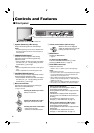
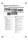
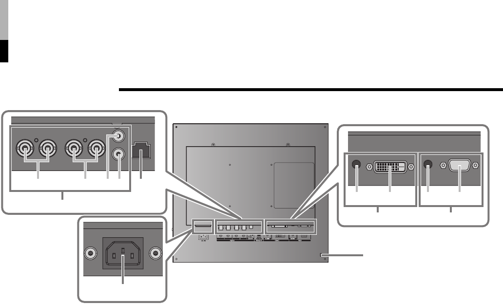
Controls and Features (cont.)
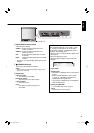
7 Rear panel
1 AC inlet
Power input connector. Connect the provided AC
power cord to an AC outlet (AC 120 V/AC 220 - 240
V, 50 Hz/60 Hz).
2 VIDEO terminals
a
VIDEO 1 terminals (BNC)
Input (IN) and output (OUT) terminals for the
composite signals.
• The IN and OUT terminals are bridge-
connected (auto termination).
• Use the AUDIO 1 terminal* for the audio
connection.
b VIDEO 2 terminals (BNC)
Input (IN) and output (OUT) terminals for the
composite signals.
• The IN and OUT terminals are bridge-
connected (auto termination).
• Use the AUDIO 2 terminal* for the audio
connection.
c AUDIO 1 terminal (pin jack)*
Input terminal for the analog audio signals.
• Use the VIDEO 1 terminal for the video
connection.
d AUDIO 2 terminal (pin jack)*
Input terminal for the analog audio signals.
• Use the VIDEO 2 terminal for the video
connection.
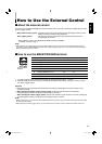
3 REMOTE (external control) terminal (MAKE/
TRIGGER)
Terminals for controlling the monitor by an external
control.
• Enables the monitor to be controlled by short-
circuiting the pin terminal in this terminal or by
inputting the pulse signal.
☞ “How to Use the External Control” on page 17
4 DVI-D terminals
e
AUDIO terminal (stereo mini jack)*
Input terminal for the analog audio signals.
NOTE:
• The built-in speaker of the monitor is monaural.
f DVI-D terminal
Input terminal for the DVI-D signals.
NOTE:
• Use a DVI-D cable with two ferrite cores
(commercially available) to avoid electromagnetic
interference.
5 RGB terminals
g
AUDIO terminal (stereo mini jack)*
Input terminal for the analog audio signals.
NOTE:
• The built-in speaker of the monitor is monaural.
h RGB terminal (D-sub 15-pin)
Input terminal for the analog RGB signals.
6 Security slot
Install a security wire to this slot.
* Equipped on LM-170 only
The illustration of the monitor is of LM-170.
03_LM170&150-EN4.indd 1003_LM170&150-EN4.indd 10 06.7.21 0:39:14 PM06.7.21 0:39:14 PM