


Masterpage:Right0
EN 17
Filename [SR-MV50U_05Name.fm]
Page 17 November 22, 2004 1:03 pm
INSTALLING YOUR NEW UNIT
It’s essential that your unit be properly connected.
1 Make sure the package contains all of the accessories listed in
“SPECIFICATIONS” on page 83.
2 Place the unit on a stable, horizontal surface.
3 Connect the unit to a TV depending on the TV and cables you
use.
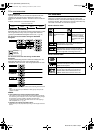
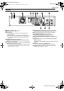
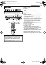
8 RF Connection
To connect to a TV with NO AV input connectors —
A Disconnect the TV antenna from the TV.
B Connect the TV antenna cable to the [VHF/UHF IN] connectors
on the rear panel of the unit via antenna splitter.
C
Connect the supplied RF cable between the [TV OUT] connector
on the rear panel of the unit and the TV’s antenna terminal.
NOTES:
● Antenna splitter is not supplied. Purchase an optional antenna
splitter.
● If you do not use antenna splitter, connect the TV antenna cable to
[VHF/UHF IN] connector. However, it is not possible to record the TV
program on the VCR deck.
● Connect the unit’s [ANT. LOOP OUT] connector to the antenna input
connector on another video unit.
8 AV Connection
To connect to a TV with AV input connectors —
A Perform A – B in “RF Connection”.
B Connect the supplied audio cable between the [AUDIO
OUTPUT] connectors on the rear panel of the unit and the TV’s
audio input connectors.
C
Connect an optional BNC video cable between the unit’s BNC
[VIDEO OUTPUT] connector and the TV’s BNC VIDEO input connector.
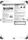
8 S-Video Connection
To connect to TV’s S-VIDEO input and AUDIO input connectors
A Perform A – B in “RF Connection”.
B Connect the unit’s [S VIDEO OUTPUT] connector to the TV’s
S-VIDEO input connector.
C Connect the unit’s [AUDIO OUTPUT] connectors to the TV’s
AUDIO input connectors.
● You can obtain high quality S-VHS pictures.
● If your TV is not stereo capable, use the unit’s [AUDIO OUTPUT]
connectors to connect to an audio amplifier for Hi-Fi stereo sound
reproduction.
8 Component Video Connection (DVD deck only)
To connect to TV’s component video input connectors
A Perform A – B in “RF Connection”.
B Connect the unit’s [COMPONENT VIDEO OUTPUT]
connectors to the TV’s component video input connectors.
C Connect the unit’s [AUDIO OUTPUT] connectors to the TV’s
AUDIO input connectors.
● You can obtain high quality component video pictures.
● If your TV is not stereo capable, use the unit’s [AUDIO OUTPUT]
connectors to connect to an audio amplifier for Hi-Fi stereo sound
reproduction.
● By using the component video connection, you can view the images
in the progressive mode. For switching to the progressive mode, refer
to “Scan Mode Set” (੬ pg. 77).
● You can also watch the images on the VCR deck in Progressive scan
mode via the component video output, refer to “VHS Progressive
Scan” (੬ pg. 45).
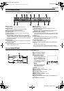
4 Plug the end of the AC power cord into an AC outlet. This unit
performs Plug & Play Set automatically. (੬ pg. 18)
● The clock and tuner channels will automatically be set when the
antenna is connected and when the AC power cord is first connected
to an AC outlet. (If “AUTO” and the channel indicator are displayed
on the front display panel before the unit is powered on, the clock and
tuner channels are being set automatically. Wait for the time to be
displayed on the front display panel before turning on the unit.)
● “LOADING” blinks on the front display panel when the AC plug of the
power cord is connected into a mains outlet and it takes
approximately 50 seconds for the unit to be turned on. This is not a
malfunction.
5 Set the video channel. The video channel is the channel on
which you can watch the picture from the unit on the TV when only
using RF connection.
With RF Connection
Set the video channel to “3 CH” or “4 CH”. To set the video
channel, perform steps A – C below:
● The video channel is preset to “3 CH”. Set to “4 CH” if the Channel 3
is used for broadcasting in your area.
With AV or S-Video Connection
Set the video channel to “– CH” (off). To set the video channel,
perform steps A – C below:
With Component Video Connection (DVD deck only)
Set the video channel to “– CH” (off). To set the video channel,
perform steps A – C below:
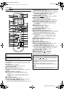
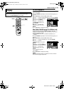
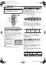
How To Set The Video Channel
A Make sure that there is no cassette in the unit.
B Press 1 to turn off the unit, then press 8 on the unit for more
than 5 seconds. “3 CH” appears on the front display panel.
C Press CH +/– on the remote control to select “3 CH”, “4 CH” or
“– CH” (off), then press ENTER. When either “3 CH” or “4 CH” is
selected, the TV/VCR indicator lights up.
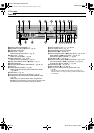
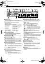
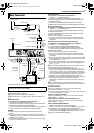
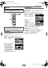
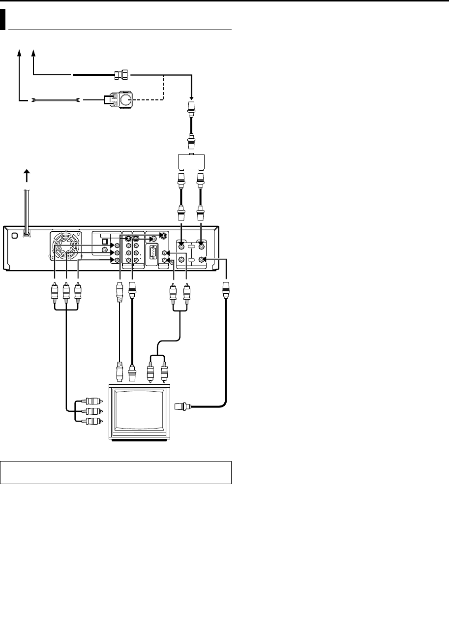
Basic Connection
THESE STEPS MUST BE COMPLETED BEFORE ANY VIDEO
OPERATION CAN BE PERFORMED.
OPTICAL
L
Antenna or Cable
Matching transformer
(not supplied)
Coaxial cable
To
[S VIDEO
OUTPUT]
AC outlet
RF cable (not supplied)
Back of unit
Flat feeder
TV
AC power cord
To 75 ohm
terminal
Antenna splitter
(not supplied)
RF cable (not supplied)
Component
video cable
(not supplied)
To
[AUDIO
OUTPUT]
To [VHF/UHF IN (DVD)]
To [TV
OUT]
RF cable
(supplied)
To [VHF/
UHF IN
(VCR)]
To
[COMPONENT
VIDEO OUT
(Y/P
B
/P
R
)]
BNC video
cable (not
supplied)
S-Video cable
(supplied)
RF cable
(not
supplied)
To [VIDEO
OUTPUT]
Audio cable
(supplied)
SR-MV50US.book Page 17 Monday, November 22, 2004 1:03 PM