


11
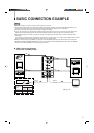
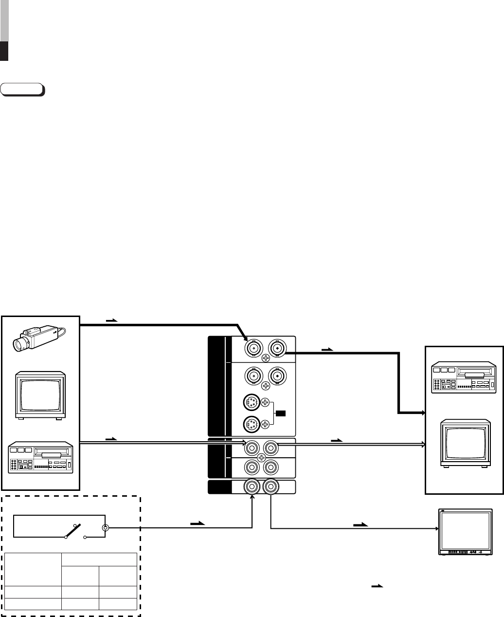
BASIC CONNECTION EXAMPLE
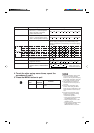
External control switch
Open circuit Short circuit
(open) (short)
ASPECT RATIO 4–3 (4:3) 16–9 (16:9)
BRIGHTNESS P.S.
OFF ON
Notes:
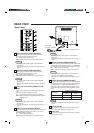
● Before connecting your system, make sure that all units are turned off.
● The illustration below shows some examples of different connections. Terminal connections may differ depending on the
component connected. Be sure to refer to the instructions provided with the unit(s) you are connecting.
● Each pair of input (IN) and output (OUT) terminals are bridge-connected.
● If you’re not connecting any equipment to a bridged output (OUT) terminal, be sure not to connect any other cables to the
bridged output (OUT) terminal as this will cause the terminating resistance switch to open (auto terminate function).
● When making a bridge connection, connect the input (IN) and output (OUT) terminals on the monitor to separate video
components.
(For example, if both terminals are connected to the same VCR, resonance may occur except during playback. This is caused
by the same video signal “looping” between the VCRs, and is not a malfunction.)
● Select the video input (Input A (VIDEO), Input B (Y/C) or Input B (VIDEO)) with the input select button on the front panel.
● The ASPECT RATIO or BRIGHTNESS P.S. function can be controlled via the REMOTE terminal. To do this, set REMOTE
SELECT in the <SET-UP MENU> mode. (Refer to page 8 and 9.)
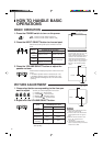
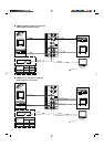
7 VIDEO A Connection Example
(Select Input A (VIDEO) button)
External control
functions
External control switch
short circuit (short)
open circuit (open)
RCA pin
Video Monitor
VCR
REMOTE
(Remote cable)
VCR
Video Monitor
Video Camera
(Audio signal cable)
Audio
Video
(Video signal cable)
: Signal Flow
Audio
Video
(Video signal cable)
(Audio signal cable)
REMOTE
(Remote cable)
OUTIN
A
B
VIDEO
A
B
AUDIO
REMOTE
OUTIN
OUT
IN
OUT
IN
IN
OUT
Y/ C
OUT
IN
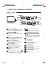
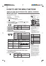
TM-2000SU
PHASECHROMABRIGHTCONTRAST MENU
INPUT SELECT
VOLUME/SELECT
– +
BA
POWER
_ON
—OFF
Y/ C VIDEOVIDEO
TM-2000SU or
TM-1600SU
<second one>