


- 10 -
1. Application Object
These instructions are applied to the AC-02SA/C chassis.
2. Notes
(1) Because this is not a hot chassis, it is not necessary to use
an isolation transformer. However, the use of an isolation
transformer will help protect test instruments.
(2) Adjustments must be done in the correct order.
(3) The input voltage of the receiver must remain at
120V±10% while adjusting.
(4) The receiver must be operated for about 20 minutes prior
to the adjustment.
[ Never operate the set over 10 minutes with a still picture
because a fluorescent material may get damage.
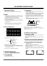
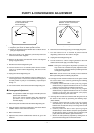
3. Focus Adjustment
(1) Set Picture condition to “APC ON”.
CONTRAST : 100
BRIGHT : 50
APC ON TINT : 55
COLOR : 0
SHARPNESS : 55
(2) Set the Aspect ratio to Wide Mode.
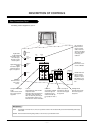
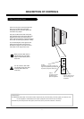
(3) Receive a Cross Hatch Pattern, adjusting the FOCUS
Knob on the flyback transformer for the best focus in the
area designated “A” above.
[ Heat run over 15 minutes before adjustment.
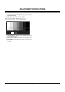
4. CUT-OFF Adjustment
(Screen Voltage Adjustment)
4-1. Test equipment
(1) Service remote control
(2) Oscilloscope(100:1) Probe
4-2. Adjustment
(1) Select EZ Adjust 3. CUT-OFF, by pressing the ADJ key on
the SVC Remote control.
When it enters to adjustment mode, the pattern from a
signal generator is being selected, it becomes with Normal
image 16:9 and the CUT-OFF DRIVE data setting 31.
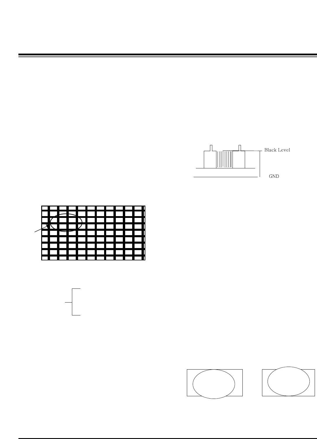
(2) Connect the oscilloscope ground lead to GND on the CPT
board and the probe to the GK pin connector of the CPT
socket.
Using the SCREEN knob on the Flyback Transformer,
adjust the black level voltage to 180±2V.
5. Deflection Adjustment
5-1. Preliminary Steps
Select EZ Adjust 1. Raster, Cent, H/V Size by using the ADJ
key on the SVC Remote control.
In the adjustment mode a Digital Pattern signal signal is
displayed.
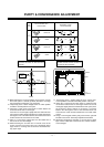
5-2. Raster V-Center(V.Center) Adjustment
Select 62. V-Postition in the adjustment mode and adjust it to
position the vertical center line in vertical center of the CPT.
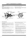
5-3. Vertical Deflection Size Adjustment
(Overscan : 10%)
(1) Select 59. V-SIZE in the adjustment mode.
(2) Adjust until the smaller inscribed circle coincides with the
outer frame of screen.
(3) Select 95. LO-VLIN or 94. UP-VLIN and adjust until the
larger inscribed circle coincides with the outer frame of
screen.
ADJUSTMENT INSTRUCTIONS
A
180±2V
CUT-OFF Adjustment
(SCREEN voltage adjustment OSCILLOSCOPE, 100:1
PROBE, VOLTS/DIV : 0.5V/DIV SEC/DIV : 5us, The TRIGGER
MODE it puts in the TV-H)
LO-VLIN UP-VLIN