25
EXTERNAL EQUIPMENT SETUP
GG
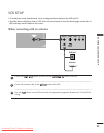
If both S-VIDEO and VIDEO sockets have been connected to
the S-VHS VCR simultaneously, only the S-VIDEO can be
received.
NOTE
!
AUDIO
VIDEO
AV 1 AV 2
ANTENNA
IN
HDMI/DVI IN 1 HDMI IN 2
EJECT PCMCIA
CARD SLOT
RS-232C IN
AUDIO
VIDEO
AV 1 AV 2
ANTENNA
IN
HDMI/DVI IN 1 HDMI IN 2
EJECT PCMCIA
CARD SLOT
RS-232C IN
L
R
S-VIDEO
VIDEO
OUTPUT
SWITCH
ANT IN
ANT OUT
AV IN 3V IN 3
L/L/MONOMONO
R
AUDIOAUDIO
VIDEOVIDEO
S-VIDEOS-VIDEO
AV IN 3
L/MONO
R
AUDIO
VIDEO
S-VIDEO
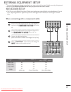
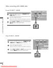
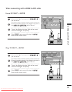
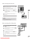
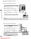
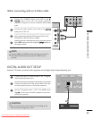
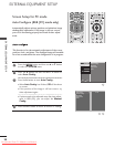
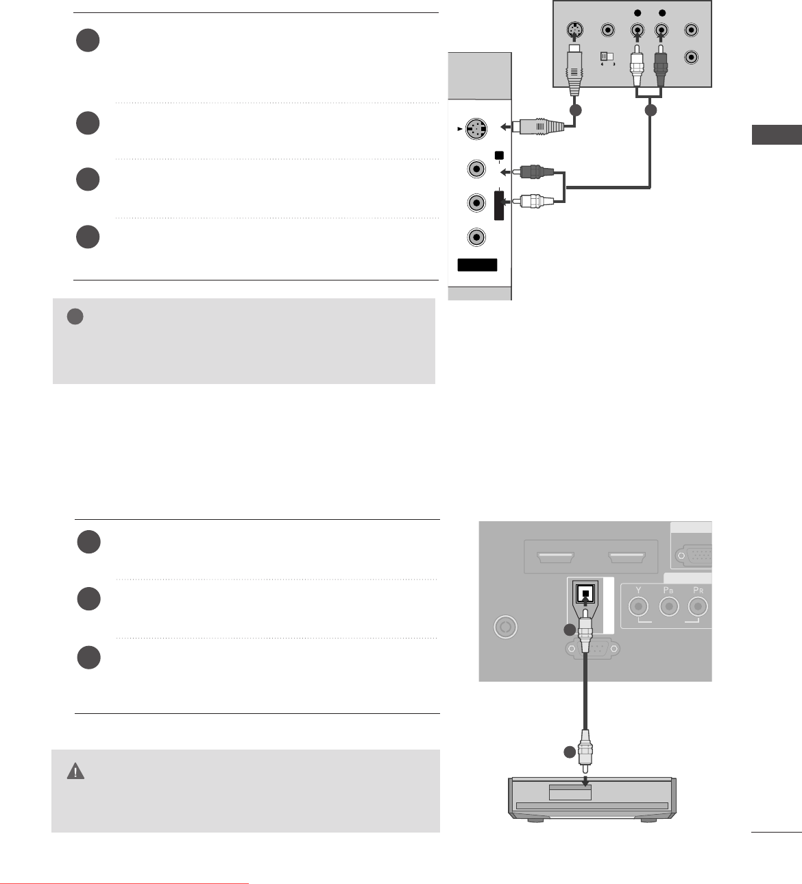
When connecting with an S-Video cable
Connect the S-VIDEO output of the VCR to the
SS--
VVIIDDEEOO
input on the set. The picture quality is
improved; compared to normal composite (RCA cable)
input.
Connect the audio outputs of the VCR to the
AAUUDDIIOO
input jacks on the set.
Insert a video tape into the VCR and press PLAY on the
VCR. (Refer to the VCR owner’s manual.)
Select
AV3 input source with using the
IINNPPUUTT
button on
the remote control.
2
3
4
1
1 2
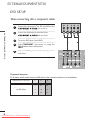
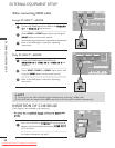
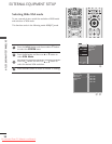
DIGITAL AUDIO OUT SETUP
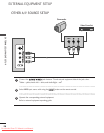
Send the TV’s audio to external audio equipment via the Digital Audio Output
(
Optical
)
port.
G
Do not look into the optical output port. Looking at the
laser beam may damage your vision.
CAUTION
RGB
(PC
R
COMP
AUDIO
VIDEOVIDEO
AV 1 AV 2
ANTENNA
IN
HDMI/DVI IN 1HDMI/DVI IN 1 HDMI IN 2HDMI IN 2
EJECT PCMCIA
CARD SLOT
RS-232C IN
(CONTROL & SERVICE)
OPTICAL
DIGITAL AUDIO OUT
Connect one end of an optical cable to the TV Digital
Audio
(
Optical
)
Output port.
Connect the other end of the optical cable to the digi-
tal audio
(
optical
)
input on the audio equipment.
Set the “TV Speaker option - Off” in the AUDIO menu.
(
G
pp..7788
). See the external audio equipment instruction
manual for operation.
2
3
1
1
2
Ofrecido por www.electromanuales.com
Downloaded From TV-Manual.com Manuals


